Method for Manufacturing a Device Comprising a Hermetically Sealed Vacuum Housing and Getter

a vacuum housing and getter technology, applied in the direction of fluid speed measurement, device details, instruments, etc., can solve the problems of tightness, intense radiation capable of damaging the bolometer, and damage to the bolometer, so as to reduce the number of manufacturing steps, and simplify the design of the device

Active Publication Date: 2017-05-18
LYNRED
View PDF13 Cites 20 Cited by
  • Summary
  • Abstract
  • Description
  • Claims
  • Application Information

AI Technical Summary

Benefits of technology

[0040]In other words, the hydrogen getter is formed or comprises a metal layer deposited on at least one of the walls of the hermetically sealed housing and at least partially exposed to the inner atmosphere of the housing. More particularly, this layer is formed on the housing window. As a variation, the cap comprises walls bearing on a substrate, typically the substrate having the microelectronic component formed thereon, the cap having a U-shaped cross-section, for example, and the metal layer is formed on the substrate. This layer advantageously comprises two portions formed in a single operation, a first portion being integrated in the assembly junction of fluxless soldering of the housing, and a second portion being in direct interaction with the inside of the housing and accordingly forming part of the getter. The soldering method is implemented in fluxless fashion on forming of the assembly to avoid the presence in the cavity, even in the state of

Problems solved by technology

However, obtaining such a pressure level requires specific techniques for the hermetic sealing of the housing.
Sintered getters require a temperature in the order of 800° C. or more, so that a general heating of the tight housing at this temperature would cause irreparable damage.
The activation of such a getter however induces an intense radiation capable of damaging the bolometers.
Indeed, the connections crossing the base

Method used


Image

  • Method for Manufacturing a Device Comprising a Hermetically Sealed Vacuum Housing and Getter
  • Method for Manufacturing a Device Comprising a Hermetically Sealed Vacuum Housing and Getter
  • Method for Manufacturing a Device Comprising a Hermetically Sealed Vacuum Housing and Getter

Examples


first embodiment

A) Sealing of the Housing with a Pumping Out of the Housing Via an Exhaust Tube

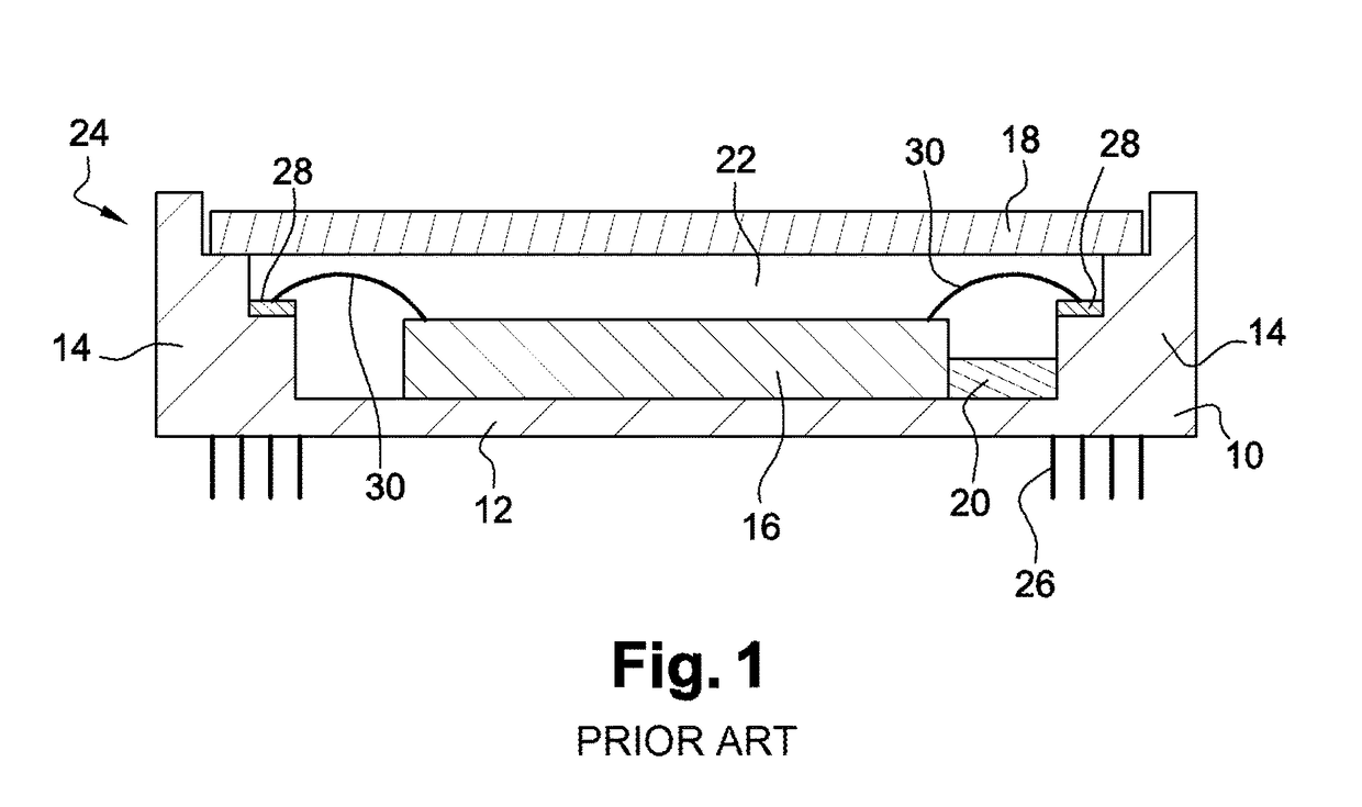
[0056]According to a method of the state of the art, the hermetically sealed housings closed by a window transparent to radiations of interest, usually made of silicon or of germanium for infrared applications, are pumped out via a tube crossing a wall of the housing, called “exhaust tube”, enabling to pump from the inner space of the housing. The housing is typically made of metallic materials or associating a metal for the walls, the bottom, and the cap, and glass and / or ceramic for the electrical paths formed in the walls, thus forming a hermetically closed enclosure once the exhaust tube has been mechanically sealed. More particularly, the window is placed on the lateral walls of the housing and attached thereto by soldering. A layer of metallic solder material is deposited for this purpose on the window and / or the lateral walls of the housing, after which a thermal and / or mechanical action is exerte...

second embodiment

B) Sealing of the Housing with a Pumping Out of the Housing According to a Method of Collective Sealing of Individual Parts

[0070]Another state of the art relative to the hermetic sealing of microelectronic components, in particular, of microbolometric imaging components, provides a collective sealing which does not use exhaust tubes to obtain vacuum in the cavity of a housing. According, for example, to document FR 2874691, it is possible to collectively assemble discrete components in a vacuum oven taken to a sufficient temperature for a duration adapted to the desired vacuum level.

[0071]As in the case of housings pumped out by an exhaust tube, the vacuum cavities contain substantially no organic material (polymers, adhesives) which excessively degas, for too long a time for the implementation of the described embodiments.

[0072]The microelectronic component is particularly fixed by fluxless soldering in the housing opposite the window transparent to infrared radiation. The preferr...


PUM

PropertyMeasurementUnit
Temperatureaaaaaaaaaa
Timeaaaaaaaaaa
Thicknessaaaaaaaaaa

Abstract

A method of manufacturing a device having a microelectronic component housed in a hermetically sealed vacuum housing, including forming a getter in said housing, pumping out and heating the device to degas elements housed in said housing, after said pumping, hermetically sealing the housing in fluxless fashion.
Further, each material forming the device likely to degas into the inner space is a mineral material, the getter is capable of substantially trapping hydrogen only and is inert to oxygen and/or to nitrogen and the heating and the sealing are performed at a temperature lower than 300° C.

Description

TECHNOLOGICAL FIELD[0001]The present description relates to the field of the hermetic sealing of microelectronic components under high vacuum, for example, detectors based on microbolometers for infrared imaging or thermometry.BACKGROUND[0002]For certain applications, microelectronic components have to operate in vacuum to achieve the desired performances. This is true, in particular, for non-cooled detectors for infrared imaging based on bolometric microbridges, called “microbolometers” hereafter. In the field of so-called “thermal” infrared detectors, it is indeed known to use one-dimensional or two-dimensional arrays of elements sensitive to infrared radiation, capable of operating at ambient temperature.[0003]A thermal infrared detector conventionally uses the variation of the electric resistivity of a thermometric material, or also known as “bolometric” according to its temperature. The unit sensitive elements of the detector, or “bolometers”, are usually in the form of membran...

Claims


Application Information

Patent Timeline
IPC IPC(8): B81B7/00G01J5/20B81C1/00
CPCB81B7/0038B81C1/00285B81C2203/0145B81B2201/0207B81C2203/019G01J5/20B81C1/00269H01L2224/48091H01L2924/00014H01L23/564H01L31/186
Inventor FAVIER, JEROMEBUNEL, DAVID
Owner LYNRED
Why Eureka
Try Eureka