Electromagnetic interference cancelling during power conversion

Inactive Publication Date: 2013-08-22
ENPHASE ENERGY
View PDF26 Cites 52 Cited by
  • Summary
  • Abstract
  • Description
  • Claims
  • Application Information

AI Technical Summary

Problems solved by technology

As a result of parasitic capacitance that links the transformer's primary and secondary windings, known as inter-winding capacitance, common mode current can flow between

Method used


Image

  • Electromagnetic interference cancelling during power conversion
  • Electromagnetic interference cancelling during power conversion
  • Electromagnetic interference cancelling during power conversion

Examples


Embodiment Construction

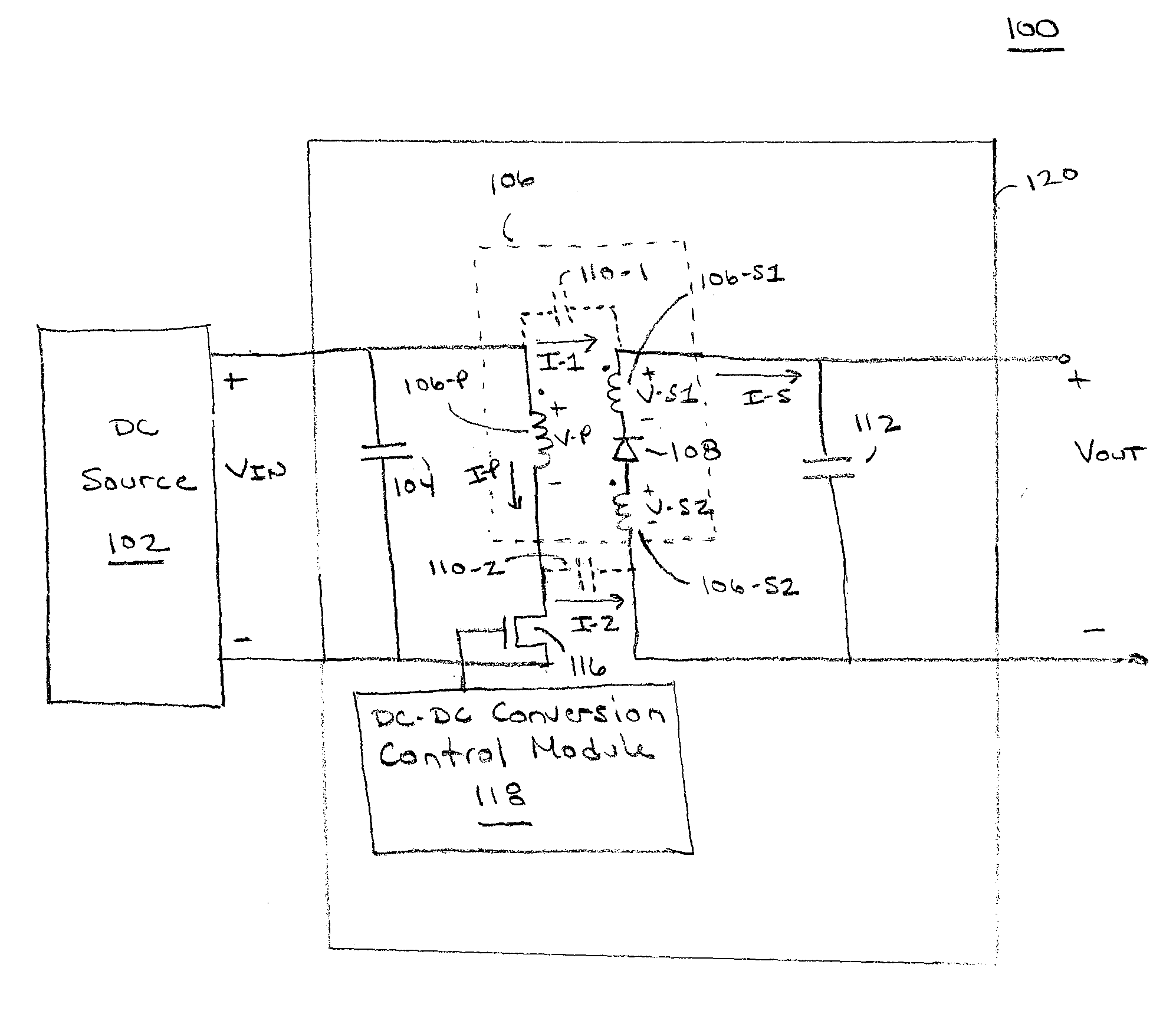
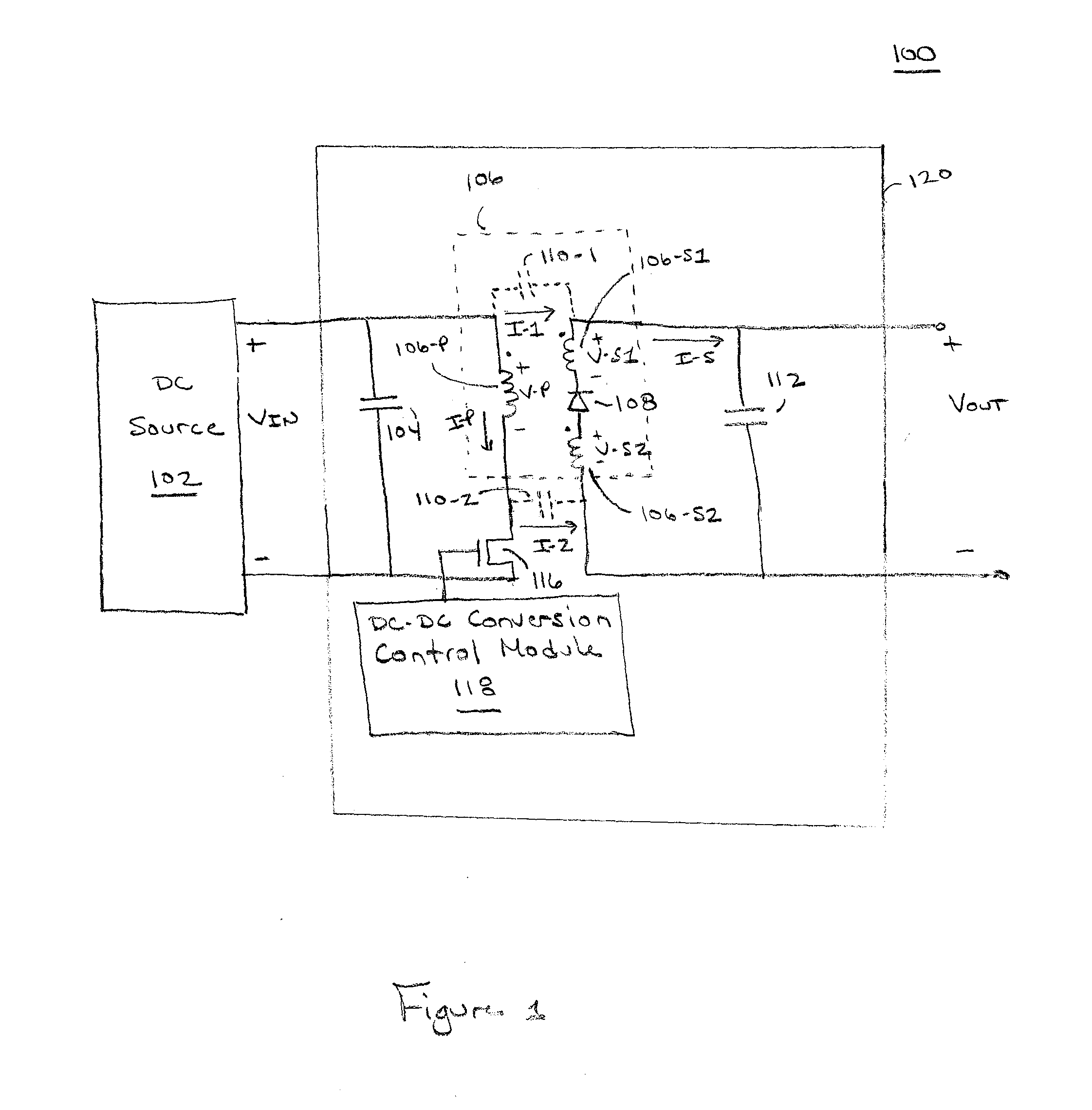
[0012]FIG. 1 is a block diagram of a power conversion system 100 in accordance with one or more embodiments of the present invention. The power conversion system 100 comprises a DC source 102 and a DC-DC converter 120. The DC source 102 may be any suitable DC source, such as an output from a preceding power conversion stage, a battery, a renewable energy source (e.g., a solar panel or photovoltaic (PV) module, a wind turbine, a hydroelectric system, or similar renewable energy source), or the like, for providing a DC voltage.

[0013]The DC-DC converter 120 may be employed in a stand-alone configuration for DC-DC power conversion as depicted in FIG. 1. Alternatively, the DC-DC converter 120 may be utilized with or as a component of other power conversion devices, such as a DC-AC inverter. For example, the DC-DC converter 120 may be a DC-DC power conversion stage within a DC-AC inverter that converts DC power from the DC source 102 to AC power.

[0014]The DC-DC converter 120 is a flyback ...


PUM


Abstract

Apparatus for cancelling electromagnetic interference (EMI) during power conversion. In one embodiment, the apparatus comprises a power converter for converting a DC input to a DC output, wherein the power converter comprises a transformer having a primary winding and a secondary winding, the secondary winding coupled to a diode such that a plurality of secondary winding voltages cause a balanced current flow through a plurality of parasitic capacitances.

Description

BACKGROUND OF THE INVENTION[0001]1. Field of the Invention[0002]Embodiments of the present disclosure relate generally to power conversion, and, in particular, to cancelling electromagnetic interference during power conversion.[0003]2. Description of the Related Art[0004]Power converters are widely used in many applications, such as renewable energy generation. Flyback converters are one type of switched mode power converter that converts DC input power to DC output power utilizing a transformer to provide galvanic isolation between the converter input and output. As a result of parasitic capacitance that links the transformer's primary and secondary windings, known as inter-winding capacitance, common mode current can flow between the windings and result in harmful common mode noise (CMN) and electromagnetic interference (EMI) that can lead to performance degradation of other electronic equipment.[0005]In order to be commercially sold, switched mode power converters such as flyback...

Claims


Application Information

Patent Timeline
IPC IPC(8): H02J1/00H02M3/335
CPCH02M1/44H02M3/335
Inventor HARRISON, MICHAEL JOHN
Owner ENPHASE ENERGY
Why Eureka
Try Eureka