Suppression of quantization noise in a fiber-optic sagnac interferometer

Active Publication Date: 2013-08-22
NORSROP GRUMAN LITEF GMBKH
View PDF2 Cites 2 Cited by
  • Summary
  • Abstract
  • Description
  • Claims
  • Application Information

AI Technical Summary

Benefits of technology

[0012]It is an object of the invention to provide a fiber-optic Sagnac interferometer in

Problems solved by technology

Noise due to limited quantization ability, also called quantization noise, results from processing by th

Method used


Image

  • Suppression of quantization noise in a fiber-optic sagnac interferometer
  • Suppression of quantization noise in a fiber-optic sagnac interferometer
  • Suppression of quantization noise in a fiber-optic sagnac interferometer

Examples


Example

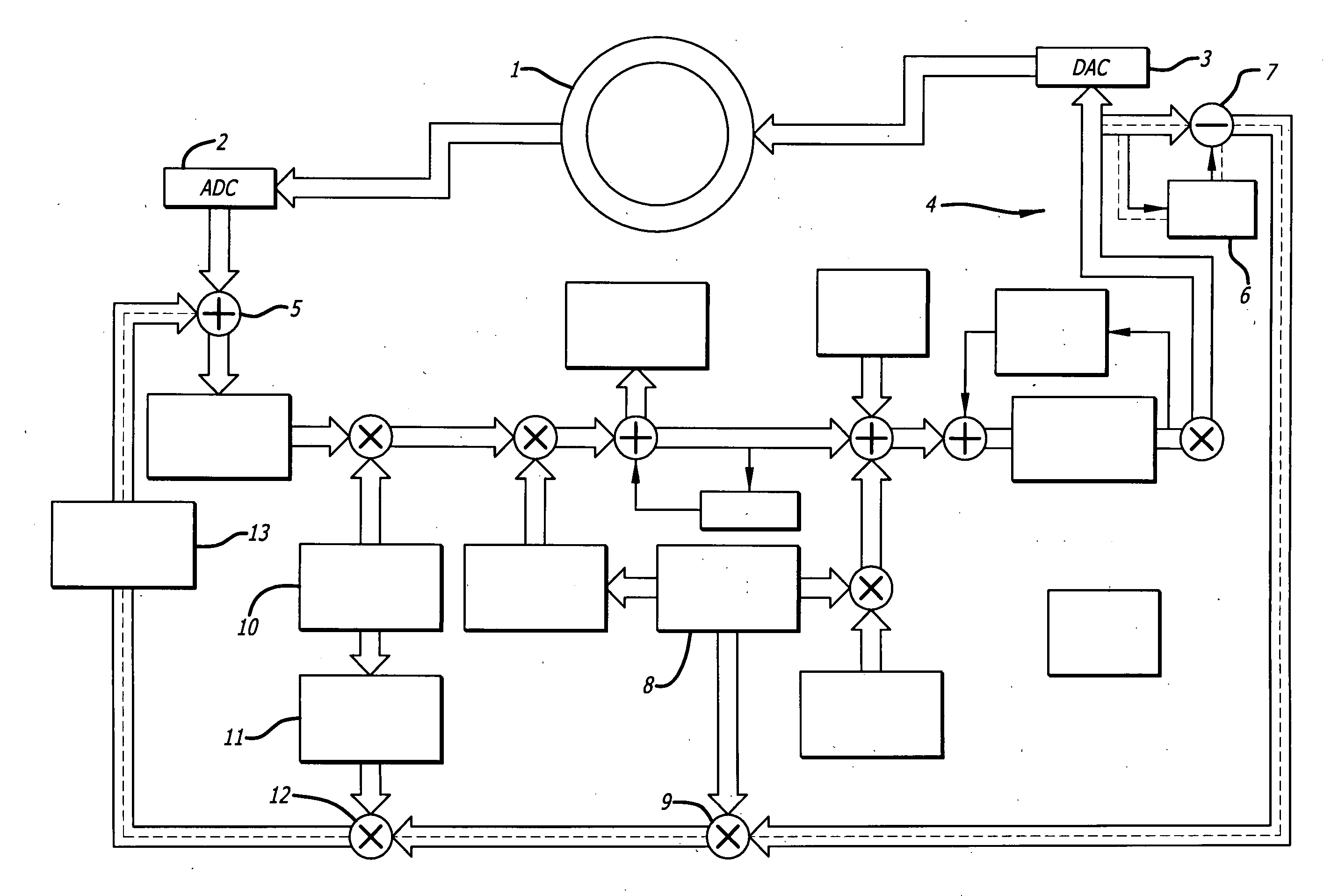
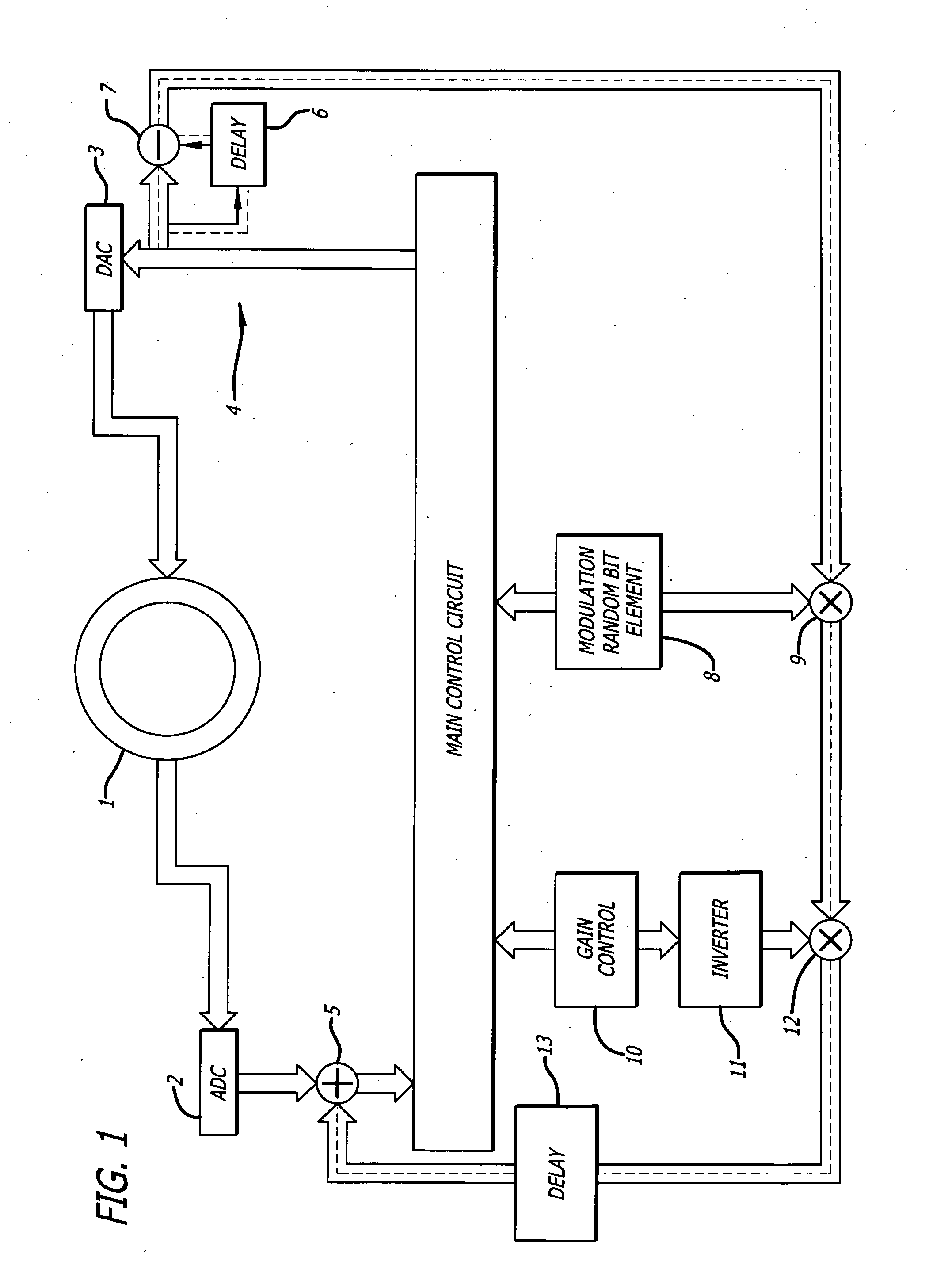
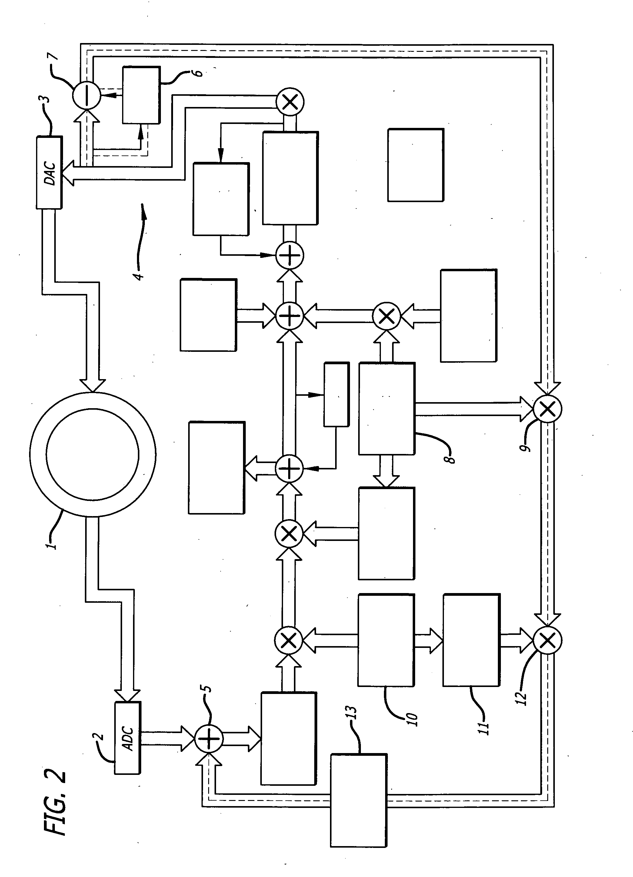
[0020]A fiber-optic Sagnac interferometer according to the invention encompasses a light source, a polarizer, a fiber coil, a photodetector device, an amplifier comprising an analog / digital converter connected downstream, a digital / analog converter, an evaluation circuit, an adder and a phase modulator. Fiber-optic ring interferometer, for example, is synonymous with fiber-optic Sagnac interferometer. The light source is preferably able to emit light at a wavelength that can be determined. Slight phase shifts are to be determined. A so-called superluminescent diode (SLD) is often used as the light source for a fiber-optic Sagnac interferometer as it possesses a higher optical bandwidth than a laser light source and, accordingly, a shorter coherence length. The advantage of a smaller coherence length (typically 25 μm), is the incoherence between the useful signal and other light signals that are created at reflection or scatter locations.

[0021]The polarizer is suitable to polarize th...


PUM


Abstract

In the case of a fiber-optic Sagnac interferometer, the output of an analog/digital converter and thus output signals processed in a main control circuit as well as a phase resetting signal for a phase modulation encompass a first word width. An input of a digital/analog converter and thus a resetting signal, which acts on the phase modulator, encompasses a second word width, which is smaller than the word width, with which the resetting and modulation signal is computed. A residual value signal comprising a third word width, which can be added to the output signal of the analog/digital converter via an adder, is obtained from the surplus, low-value bits.

Description

BACKGROUND[0001]1. Field of the Invention[0002]The present invention relates to fiber-optic Sagnac interferometers. More particularly, the invention pertains to a Sagnac interferometer and a method for controlling a Sagnac interferometer.[0003]2. Description of the Prior Art[0004]Fiber-optic Sagnac interferometers are routinely employed in aircraft and water craft. Their use in land craft is also possible. Such devices offer autonomous determination of position in space, allowing accurate vehicle position determination when the speed is known without requiring external data (e.g. a GPS signal or satellite communication).[0005]Fiber-optic Sagnac interferometers are generally integral parts of inertial navigation systems for determining the position or rotary motion of objects in space. Such determination is based on the association of rotation rates and accelerations acting on an object with reference to the three spatial axes of the inertial navigation system. With knowledge of rota...

Claims


Application Information

Patent Timeline
IPC IPC(8): G01C19/72
CPCG01C19/72G01C19/721G01C19/726
Inventor DEPPE-REIBOLD, OLAF
Owner NORSROP GRUMAN LITEF GMBKH
Why Eureka
Try Eureka