Aircraft propulsion system nacelle

a propulsion system and nacelle technology, applied in the field of aircraft propulsion systems, can solve the problems of limiting the diameter of the fan which can be employed on the engine, outweighing the reduction in fuel consumption, and limiting the bypass ratio to increase, so as to increase the diameter of the fan and increase the thrust output. , the effect of decreasing the radial thickness of the nacelle structur

Active Publication Date: 2013-08-22
ROLLS ROYCE PLC
View PDF8 Cites 21 Cited by
  • Summary
  • Abstract
  • Description
  • Claims
  • Application Information

AI Technical Summary

Benefits of technology

[0018]A conventional turbofan engine nacelle employs a monocoque type construction and has a maximum nacelle depth of approximately 300 mm (12 in). The space within the nacelle is used to accommodate various engine ancillaries and a thrust reverser mechanism. Relocating these engine ancillaries to the core engine and providing reverse thrust provision through a variable pitch fan assembly enables the nacelle structure to be formed as a monolithic structure which can be made significantly thinner in the radial direction, and therefore lighter, than a conventional nacelle assembly. For example, a monolithic nacelle structure according to the present invention has a depth of only approximately 100 mm (4 in).
[0063]In the present invention the use of a variable pitch fan (in which the fan blade pitch angle may be reversed) enables the fan assembly to direct the thrust forwards.

Problems solved by technology

However, there is a limit to how much the bypass ratio can be increased as eventually the weight and drag penalties associated with the size of the required engine nacelle outweigh the reduction in fuel consumption.
This nacelle depth, in combination with the need to maintain a minimum safe ground clearance, limits the diameter of fan which can be employed on the engine.

Method used


Image

  • Aircraft propulsion system nacelle
  • Aircraft propulsion system nacelle
  • Aircraft propulsion system nacelle

Examples


Embodiment Construction

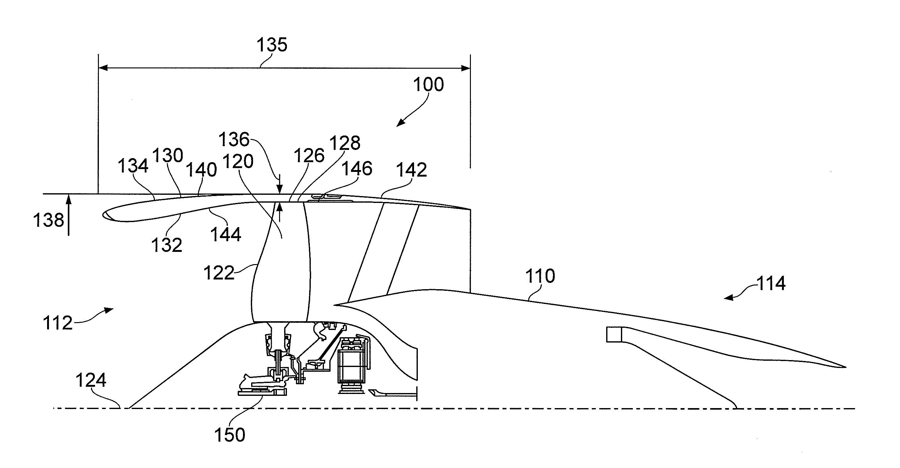
[0074]Referring to FIGS. 3 and 4, an aircraft propulsion system nacelle according to a first embodiment of the invention is designated generally by the reference numeral 100.

[0075]The aircraft propulsion system nacelle 100 comprises an engine assembly 110, a fan assembly 120 which is operatively connected to the engine assembly 110, and a nacelle structure 130 which circumferentially encloses the fan assembly 120. The engine assembly 110 has an inlet 112 and an exhaust 114.

[0076]In this embodiment of the invention, the engine assembly 110 is a gas turbine engine having a conventional three-shaft configuration and having an axis of rotation 124.

[0077]In the following description, the term ‘axially’ is to be understood to relate to the direction of the axis of rotation 124. Similarly, the terms ‘forward’ and ‘rearward’ are to be understood to refer to the inlet 112 and exhaust 114 ends of the engine assembly 110 respectively.

[0078]The fan assembly 120 comprises a plurality of fan blad...


PUM

PropertyMeasurementUnit
depthaaaaaaaaaa
depthaaaaaaaaaa
diameteraaaaaaaaaa

Abstract

An aircraft propulsion system has an engine assembly having an axis of rotation, a fan assembly operatively connected to the engine assembly and comprising a plurality of fan blades arranged circumferentially around the axis of rotation and a monolithic nacelle assembly which circumferentially encloses the fan assembly. The propulsion system has a ratio of fan assembly outer diameter to nacelle assembly outer diameter of at least 0.87. As a result, the propulsion system provides for a significantly larger fan assembly outer diameter for a given nacelle assembly outer diameter than a conventional prior art turbofan engine, thereby increasing the specific power output or the bypass ratio of the propulsion system, which will result in improved propulsive efficiency without an increase in nacelle drag.

Description

[0001]This invention claims the benefit of UK Patent Application No. 1202790.0, filed on Feb. 20, 2012, which is hereby incorporated herein in its entirety.FIELD OF THE INVENTION[0002]This invention relates to aircraft propulsion systems and particularly, but not exclusively, to aircraft propulsion systems which utilise ducted turbofan type engines generally characterised by a high bypass ratio.BACKGROUND TO THE INVENTION[0003]As shown in FIG. 1, an axial flow gas turbine turbofan engine 10 comprises an air intake 11, a low pressure compressor (or fan) 12, an intermediate pressure compressor 13, a high pressure compressor 14, a combustor 15, a high pressure turbine 16, an intermediate pressure turbine 17, a low pressure turbine 18, and an exhaust nozzle 19. A nacelle assembly 20 encloses the fan 12.[0004]In operation, air is drawn into the engine 10 through the intake 11 and accelerated by the fan 12, to produce two air flows: a first air flow which enters the intermediate pressure ...

Claims


Application Information

Patent Timeline
Patent Type & Authority Applications(United States)
IPC IPC(8): F04D29/40
CPCF02C7/04Y02T50/672F04D29/40F04D29/526F05D2220/36F05D2300/171B64D29/00B64D2033/0206B64D2033/0286F05D2230/53F05D2300/121F05D2300/603F05D2300/133Y02T50/60
Inventor EVANS, DALE EDWARD
Owner ROLLS ROYCE PLC
Why Eureka
Try Eureka