Method and system for defining a magnetoresistive junction

a technology of magnetoresistive junction and method, which is applied in the field of method and system for defining a magnetoresistive junction, can solve the problems of oxide layer, adversely affecting the performance of the magnetoresistive junction, damage to the layers in the stack,

Active Publication Date: 2013-08-22
WESTERN DIGITAL TECH INC
View PDF7 Cites 152 Cited by
  • Summary
  • Abstract
  • Description
  • Claims
  • Application Information

AI Technical Summary

Problems solved by technology

Ion milling may cause damage to the layers in a stack, particularly to oxide layers.
This damage to the barrier layer 16 may adversely affect performance of the magnetoresistive junction 10.
In addition, if the redeposition is not cleaned by the second ion milling, then metallic redeposition across the barrier layer 16 may result in shorting of the magnetoresistive junction 10.
However, if the redeposition is cleaned, then the additional ion mill may further damage the barrier layer 16.
As a result, the barrier layer 16 is exposed to more milling during the single-angle mill and experiences greater damage.
Thus, a conventional magnetoresistive junction that has a steep (large) junction angle and / or which is formed using a small milling angle is more likely to be damaged during ion milling that defines the junction.
The conventional ion mill process may also create an undesirable junction profile.
Consequently, performance of the read transducer 10 may be adversely affected.
At higher densities, the photolithography utilized to repeatably obtain a mask having a small width with limited variations may be difficult to achieve.
Consequently, fabrication of the conventional magnetoresistive junction 10 may be more problematic.
However, such an oxidation may result in a relatively thick oxidation layer on the sides of the conventional magnetoresistive junction 10.
Consequently, biasing of the magnetoresistive junction using a hard bias layer (not shown in FIG. 1) may be adversely affected.

Method used


Image

  • Method and system for defining a magnetoresistive junction
  • Method and system for defining a magnetoresistive junction
  • Method and system for defining a magnetoresistive junction

Examples


Embodiment Construction

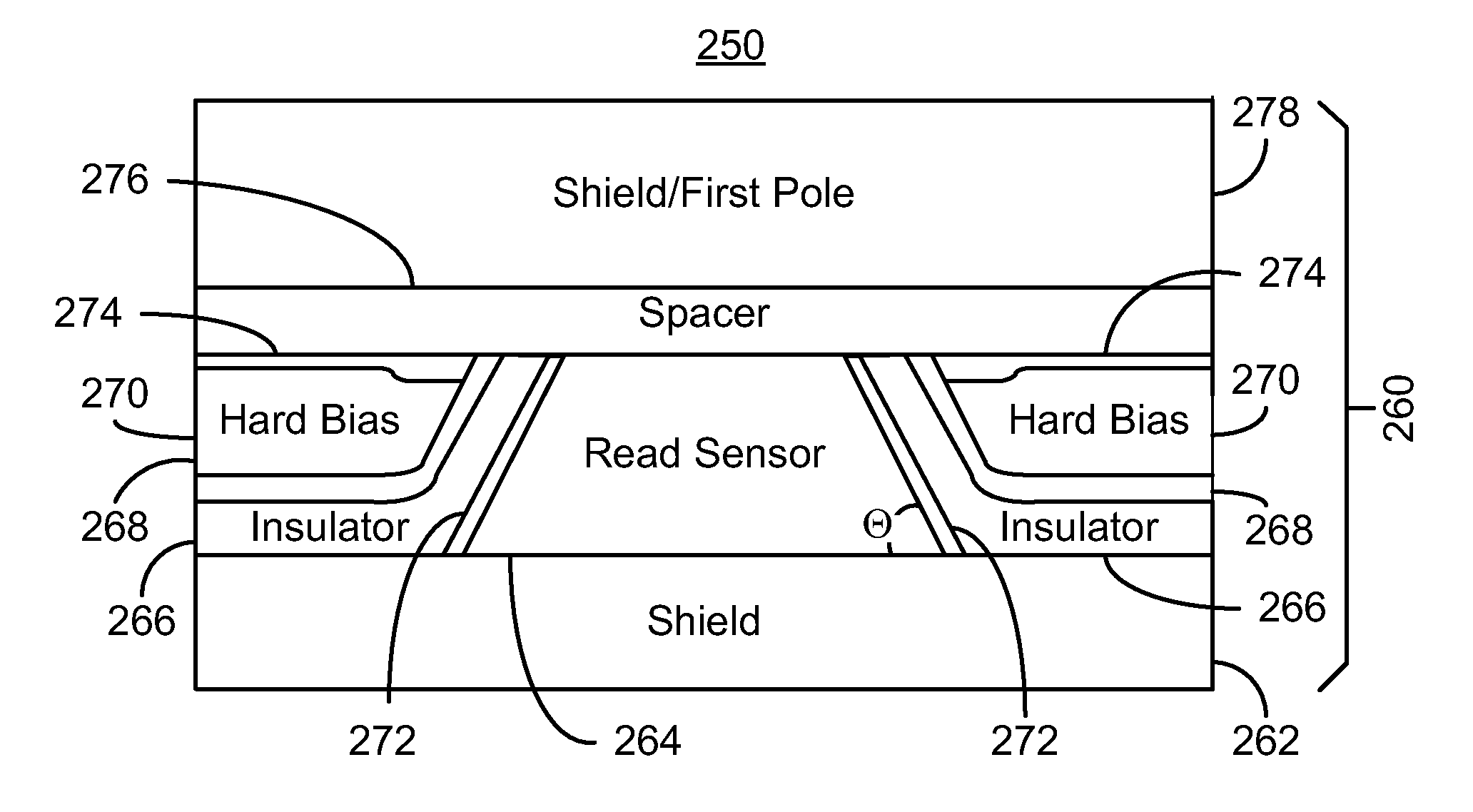
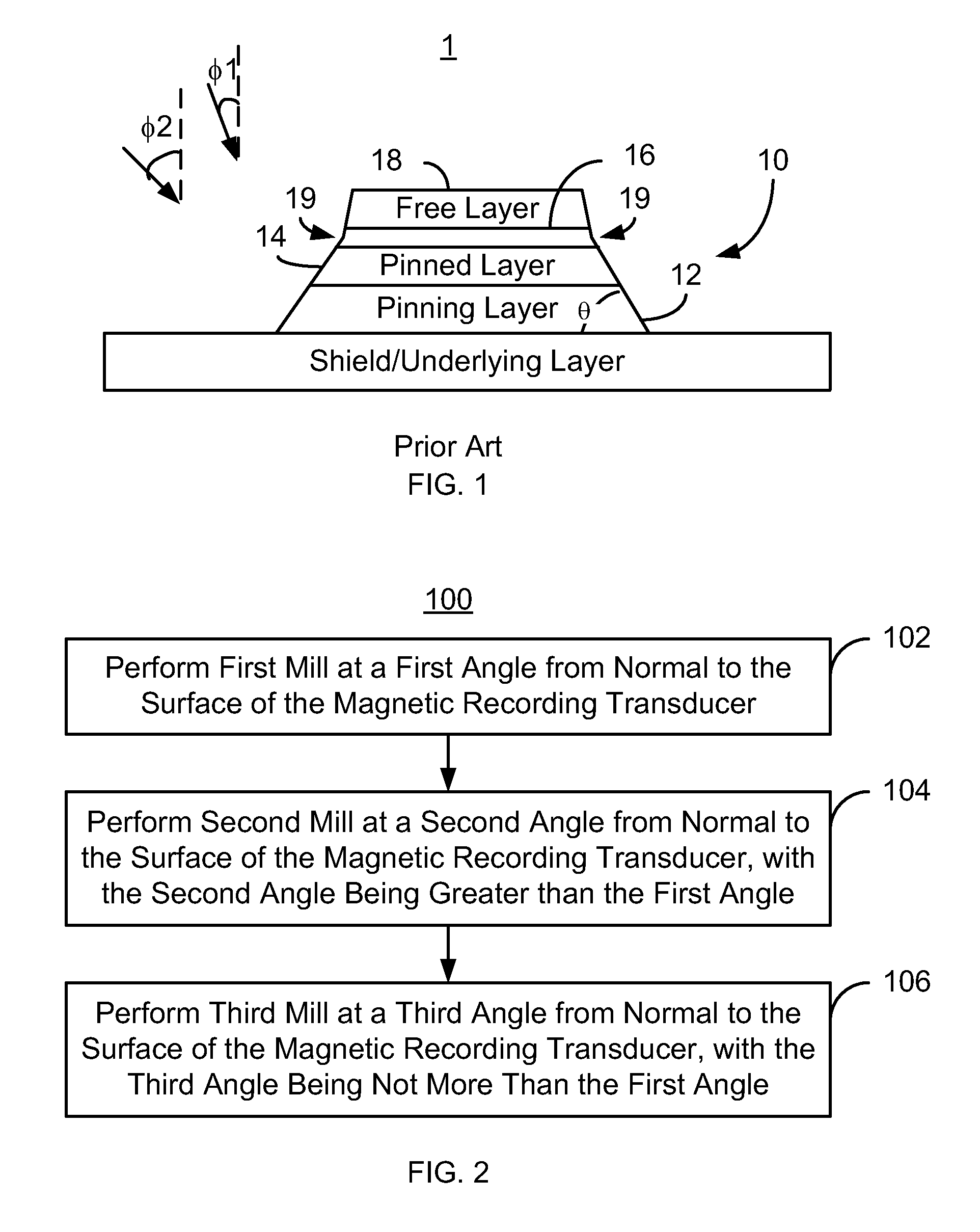
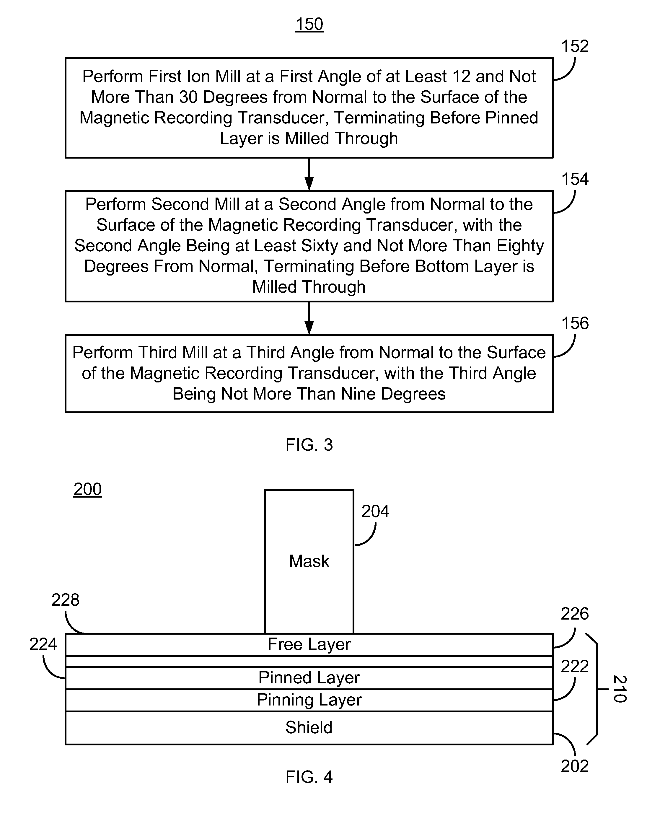
[0015]FIG. 2 is a flow chart of an exemplary embodiment of a method 100 for defining a magnetoresistive junction. For simplicity, some steps may be omitted. The magnetoresistive junction may be part of a read transducer (not shown in FIG. 1). The read transducer may be part of a merged head that also includes a write transducer (not shown in FIG. 1) and resides on a slider (not shown in FIG. 1). The method 100 also may commence after formation of other structures of the read and / or write transducer. The method 100 is also described in the context of providing a single magnetoresistive junction. However, the method 100 may be used to fabricate multiple magnetoresistive junctions at substantially the same time. The method 100 is also described in the context of particular layers. However, in some embodiments, such layers may include sub-layer(s) and the magnetoresistive junction may include additional layers. For example, a free or pinned layer may be a synthetic layer including multi...


PUM

PropertyMeasurementUnit
thickaaaaaaaaaa
thickaaaaaaaaaa
widthaaaaaaaaaa

Abstract

A method and system define a magnetoresistive junction in a magnetic recording transducer. The method and system include performing a first mill at a first angle from a normal to the surface of the magnetic recording transducer. A second mill is performed at a second angle from the normal to the surface. The second angle is larger than the first angle. A third mill is performed at a third angle from the normal to the surface. The third angle is not larger than the first angle.

Description

CROSS REFERENCE TO RELATED APPLICATIONS[0001]This application is a divisional of U.S. patent application Ser. No. 12 / 147,450 (Atty. Docket No. F3482), filed on Jun. 26, 2008, which is hereby incorporated by reference in its entirety.BACKGROUND[0002]FIG. 1 depicts a conventional magnetoresistive transducer 1 including a conventional magnetoresistive junction 10. For clarity, FIG. 1 is not drawn to scale. Magnetoresistive junctions 10, such as tunneling magnetoresistive (TMR) junctions, are used as read sensors in the conventional read transducer 1. Typically, conventional magnetoresistive junctions are formed by blanket depositing the layers for the conventional magnetoresistive junctions. This stack of layers typically includes layers for pinning layer 12 such as an antiferromagnetic (AFM) layer, a magnetic pinned layer 14, a nonmagnetic spacer layer 16, and a magnetic free layer 18. Other layers (not shown) might also be included in the magnetoresistive junction. For a conventional...

Claims


Application Information

Patent Timeline
Patent Type & Authority Applications(United States)
IPC IPC(8): G11B5/39
CPCG11B5/3906G11B5/398G01R33/093Y10T428/1114Y10T29/49046Y10T29/49044G11B5/3909
Inventor LI, GUANXIONGDANG, XIAOZHONGPAKALA, MAHENDRASHEN, YONG
Owner WESTERN DIGITAL TECH INC
Why Eureka
Try Eureka