
Methods and systems for maintaining a storage volume with holes and filling holes

a storage volume and hole technology, applied in the field of composite nonvolatile memory management methods and systems, can solve the problems of reducing system performance, reducing system performance, and slow, and inexpensive magnetic hard drives can be combined with a small, fast but expensive storage device,

Active Publication Date: 2013-08-22
APPLE INC
View PDF7 Cites 12 Cited by
  • Summary
  • Abstract
  • Description
  • Claims
  • Application Information

AI Technical Summary

Benefits of technology

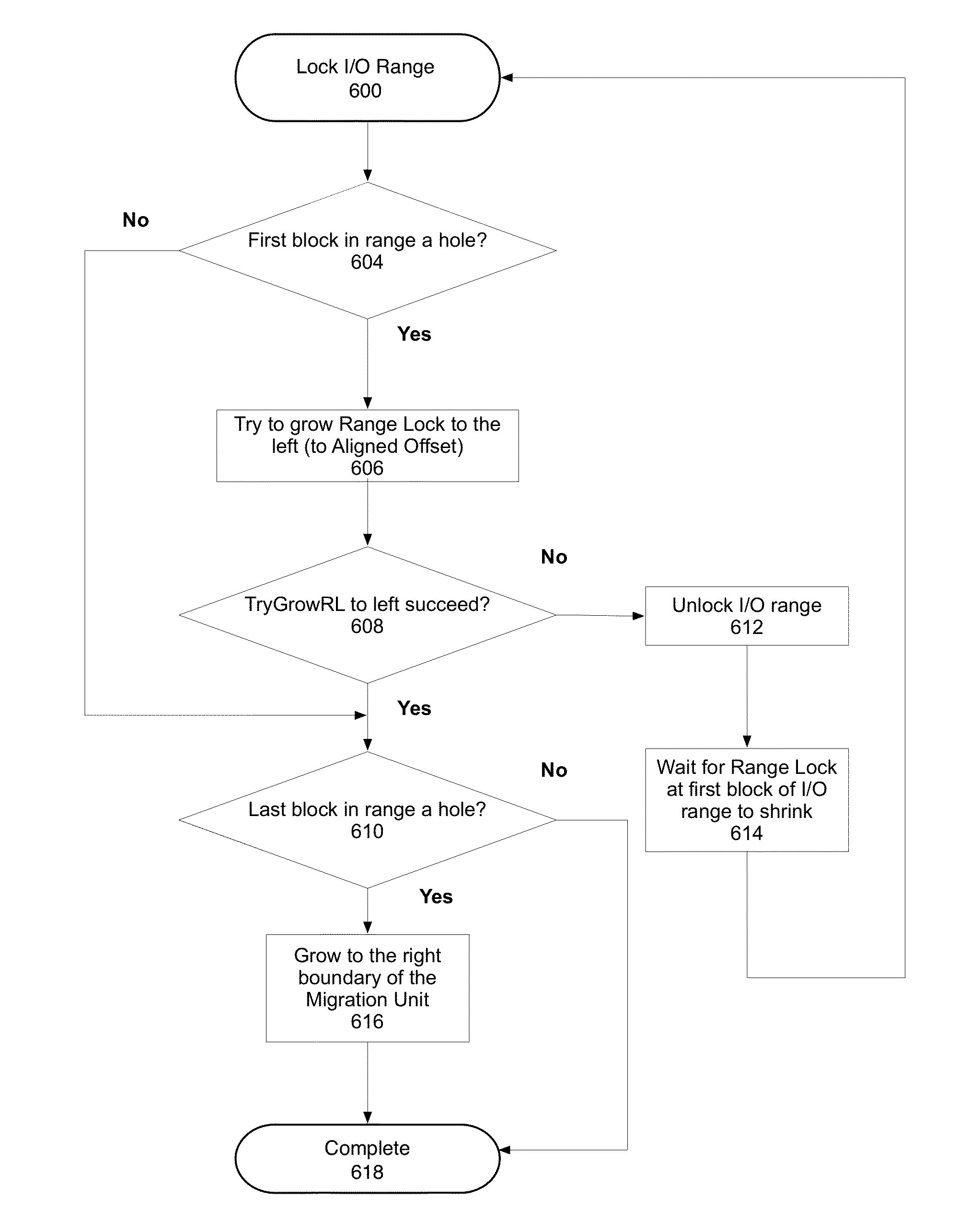
The patent describes a method for managing access to different types of non-volatile storage devices. One aspect is a method of allocating sparse blocks of a logical volume until they are needed, using a method called sparse hole filling. The method uses a range lock service, which is represented by an ordered search tree. Each node in the tree contains information about a range that is currently locked, including its offset and length, and a conditional variable for other threads to wait on. The method also includes queues for waiting and waiting for the range to shrink. Overall, the patent provides a way to optimize the allocation of data across different types of storage devices, improving performance and reliability.

Problems solved by technology

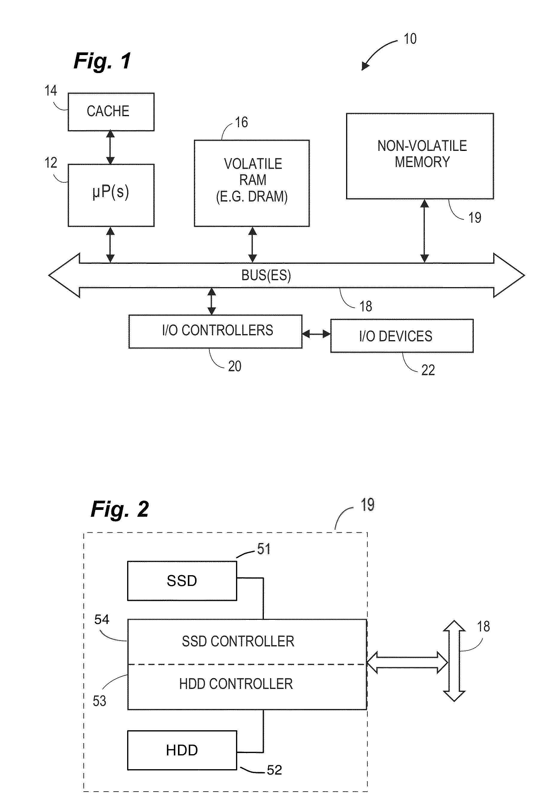
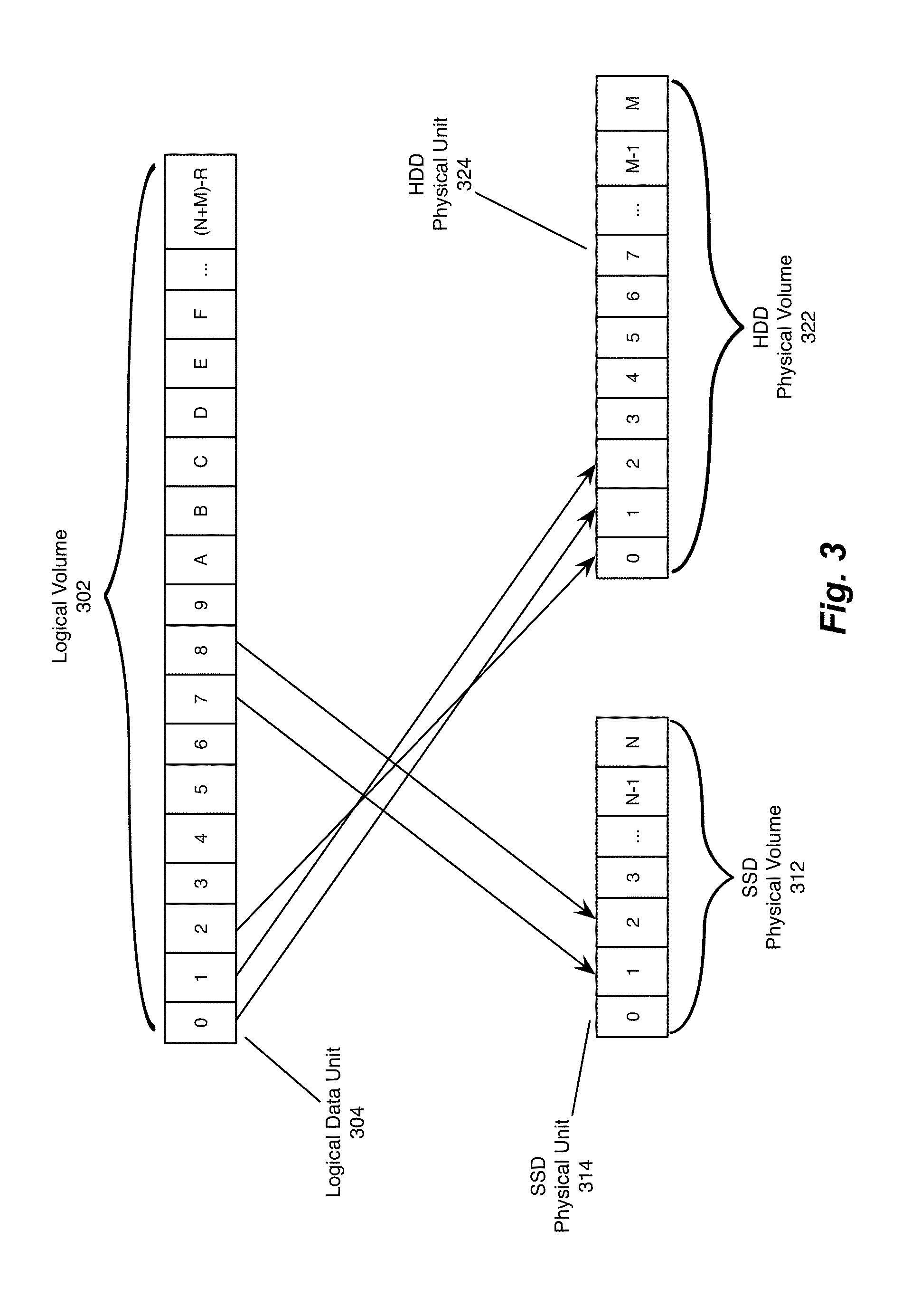
In a composite disk system, a large, slow, and inexpensive magnetic hard drive can be combined with a small, fast but expensive storage device, such as a solid state drive to form a logical volume.
One element of I / O overhead in managing storage devices is the serializing of disk operations enforced by byte range locking algorithms, which preserve data integrity by requiring atomic operations on certain storage byte ranges.
When one process has a lock on a range of addresses, other processes may not be able to access the locked address range.
Accordingly, one process's byte-range locks can block a different process's I / O operation if the operations are to overlapping addresses, which can reduce system performance.

Method used


Image

  • Methods and systems for maintaining a storage volume with holes and filling holes
  • Methods and systems for maintaining a storage volume with holes and filling holes
  • Methods and systems for maintaining a storage volume with holes and filling holes

Examples


Embodiment Construction

[0025]Various embodiments and aspects of managing a composite, non-volatile data storage device will be described with reference to details discussed below. The accompanying drawings will illustrate the various embodiments. The following description and drawings are illustrative of the invention and are not to be construed as limiting the invention. Numerous specific details are described to provide a thorough understanding of various embodiments of the present invention. However, in certain instances, well-known or conventional details are not described in order to provide a concise discussion of embodiments of the present invention.

[0026]Reference in the specification to “one embodiment” or “an embodiment” means that a particular feature, structure, or characteristic described in conjunction with the embodiment can be included in at least one embodiment of the invention. The appearances of the phrase “in one embodiment” in various places in the specification do not necessarily all...


PUM


Abstract

In one embodiment, a method for managing access to a fast non-volatile storage device, such as a solid state device, and a slower non-volatile storage device, such as a magnetic hard drive, can include a method of managing a sparse logical volume in which unmapped blocks of the logical volume are not allocated until use. In one embodiment, a method of sparse hole filling operates in which range locks are dynamically adjusted to perform allocations for sparse hole filling, and then re-adjusted to perform standard operations using a byte range lock. In one embodiment, a high level data structure can be used in the range lock service in the form of an ordered search tree, which could use any search tree algorithm, such as red-black tree, AVL tree, splay tree, etc.

Description

CROSS-REFERENCE[0001]The present application is related to, and claims the benefit of provisional application Ser. No. 61 / 599,930 filed Feb. 16, 2012, and provisional application Ser. No. 61 / 699,166, filed Sep. 10, 2012, both of which are incorporated herein by reference. The present application is also related to co-pending application Ser. No. 61 / 599,927 filed on Feb. 16, 2012, which is incorporated herein by reference.BACKGROUND OF THE INVENTION[0002]The present invention relates to methods for managing storage of data in a composite non-volatile memory that is a composite of a slow memory device and a fast memory device. In a composite disk system, a large, slow, and inexpensive magnetic hard drive can be combined with a small, fast but expensive storage device, such as a solid state drive to form a logical volume. Techniques to manage data transfer between memory devices have to take into account the overhead that I / O operations on and between the devices can present, and manag...

Claims


Application Information

Patent Timeline
IPC IPC(8): G06F12/14G06F12/16
CPCG06F3/061G06F3/064G06F3/0685G06F3/0647G06F3/0644
Inventor WANG, WENGUANGMAJNEMER, DAVID A.
Owner APPLE INC
Learn More