Awning comprising a vibration-damped drive

a technology of vibration-damping drive and awning, which is applied in the direction of sunshades, buildings, constructions, etc., can solve the problems of increasing the complexity of the system, increasing the cost of installation, so as to prevent excessive compression, improve the wear resistance of the vibration-damping device according to the invention, and avoid permanent loss of foam structure and flexibility

Inactive Publication Date: 2013-08-29
SCHMITZ WERKE
View PDF8 Cites 3 Cited by
  • Summary
  • Abstract
  • Description
  • Claims
  • Application Information

AI Technical Summary

Benefits of technology

[0012]The mutual positive engagement of mounting head, radial damping member and support head in the direction of rotation of these components ensures a complete vibration decoupling between the motor drive arranged in the fabric shaft and the holding bracket. Both support head and mounting head as well as the radial damping member are fully integrated in the fabric shaft; this ensures that unlike in prior art, the fabric shaft does not have to be shortened. Therefore the shaded area is not reduced when using the inventive awning
[0011]This object is achieved by providing a vibration insulation device which is completely arranged inside the fabric shaft between the motor drive and the holding bracket used for fixing the latter. The motor drive is protected against rotation in the fabric shaft by means of a support head. Together with the support head, a radial damping member of a vibration-damping, flexible material positively engages the motor drive in the direction of rotation. This assembly is then fixed to the holding bracket by means of a mounting head which is arranged thereto in a non-rotating manner and positively engages the damping unit in the direction of rotation.
[0014]According to a preferred embodiment of the invention, the support head is designed as a non-round external profile part extending in the axial direction of the fabric shaft, with the radial damping member—which is in the shape of a ring-like closed component—being slid on said external profile part. The radial damping member is formed by a plurality of radial damping rings which are arranged in a row when seen in the axial direction of the fabric shaft, thus ensuring an improved mountability. Arranged in the fabric shaft, both support head and mounting head can be made longer or shorter when seen in the axial direction, depending on the desired damping properties. The longer support head and mounting head, the longer the radial damping member, in other words the higher the number of radial damping rings arranged in a row.
[0015]In a preferred embodiment, the mounting head—similar to the support head—can be designed as a non-round, bell-shaped internal profile part extending in the axial direction of the fabric shaft, with the radial damping member—which is in the shape of a ring-like, closed component—being slid into said internal profile part together with the support head. The three components of the vibration insulation device, mounting head, radial damping member and support head, are therefore coaxially arranged one inside the other, thus ensuring a very compact design of the vibration insulation device.
[0016]A particularly effective transmission of torque between the support head and the radial damping member is achievable by means of the star-shaped cross-section of the two components, thus ensuring a reliable transmission of the shoring moment applied by the motor drive.
[0017]Likewise, designing the cross-section of the mounting head as an approximately blossom-shaped internal profile part with a corresponding external cross-section of the radial damping member ensures a stable connection between the two components for an optimal transmission of the momentum generated when the motor is mounted.
[0023]According to a final preferred embodiment, a mounting sleeve is mounted for rotation on the mounting head of the vibration insulation device for carrying the fabric shaft. Therefore the mounting head has a double function which provides a considerable constructional advantage. Mounting the fabric shaft to the mounting head via the mounting sleeve ensures that the fabric shaft is supported in an optimal off-center position which facilitates an even and smooth rotational movement of the fabric shaft.

Problems solved by technology

Particularly when awning installations are operated automatically using intelligent control systems, the sound produced during operation poses a problem.
This noise is extremely disturbing to the tenants of the building as it disturbs their peace or even interrupts their sleep.
The drawback of this low-vibration bearing is that it is positioned between the holding bracket of the awning and the motor head.
Due to the additional acoustic components, this system is more complex than a passive vibration and noise damping system.

Method used


Image

  • Awning comprising a vibration-damped drive
  • Awning comprising a vibration-damped drive
  • Awning comprising a vibration-damped drive

Examples


Embodiment Construction

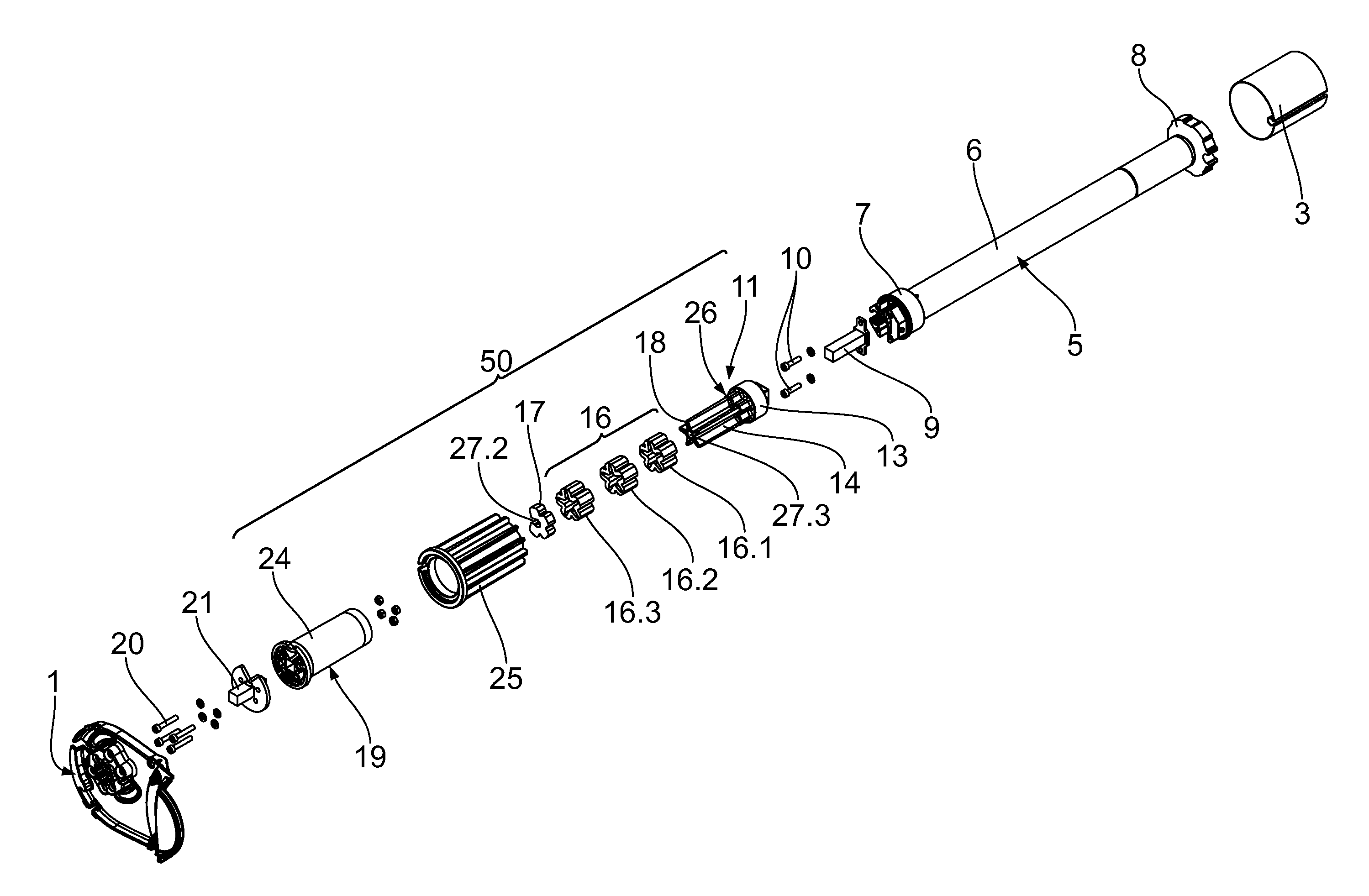
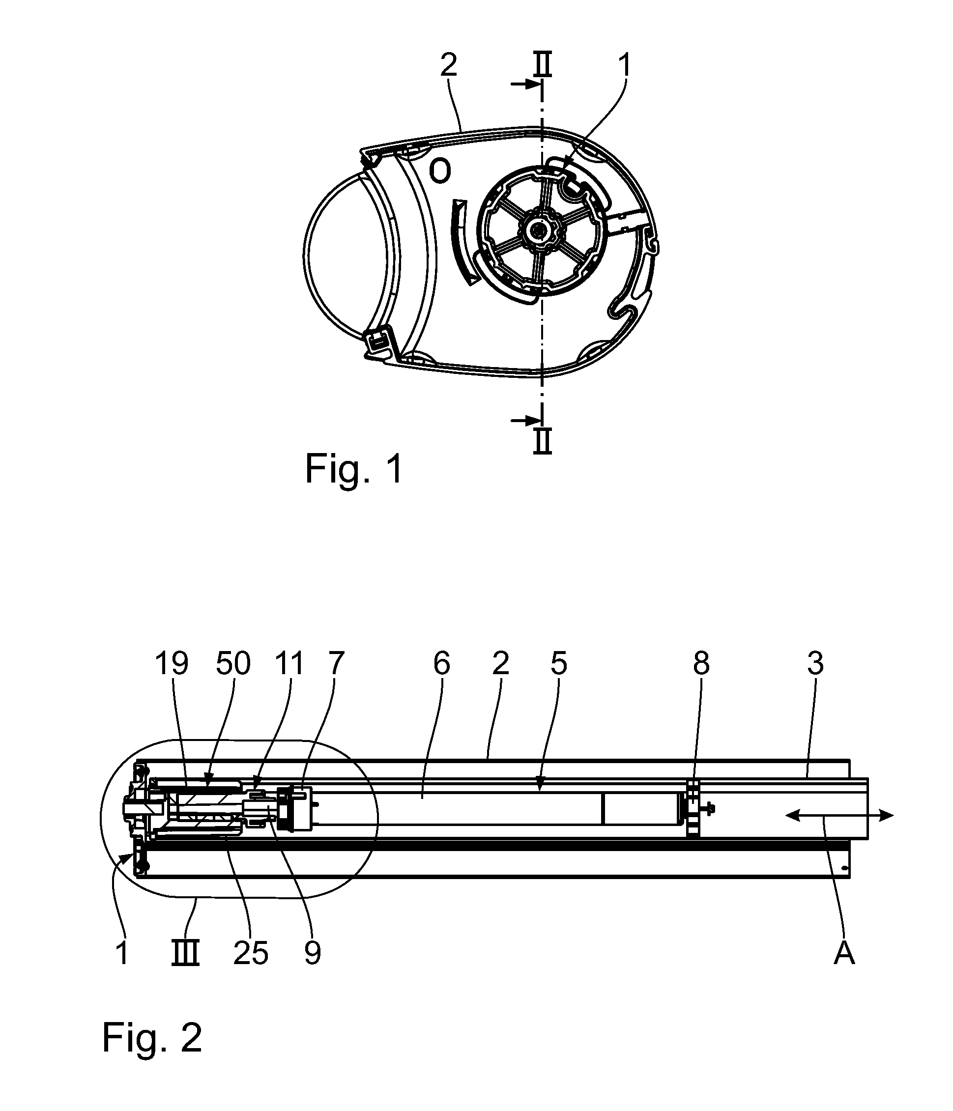
[0033]With reference to FIGS. 1 to 4, the partially shown awning comprises two holding brackets 1 arranged on a base member not shown in greater detail, of which only one is shown in the drawings. For clarity, the mentioned base member by means of which the awning is secured to a housing wall or the like is omitted from the Figures as well.

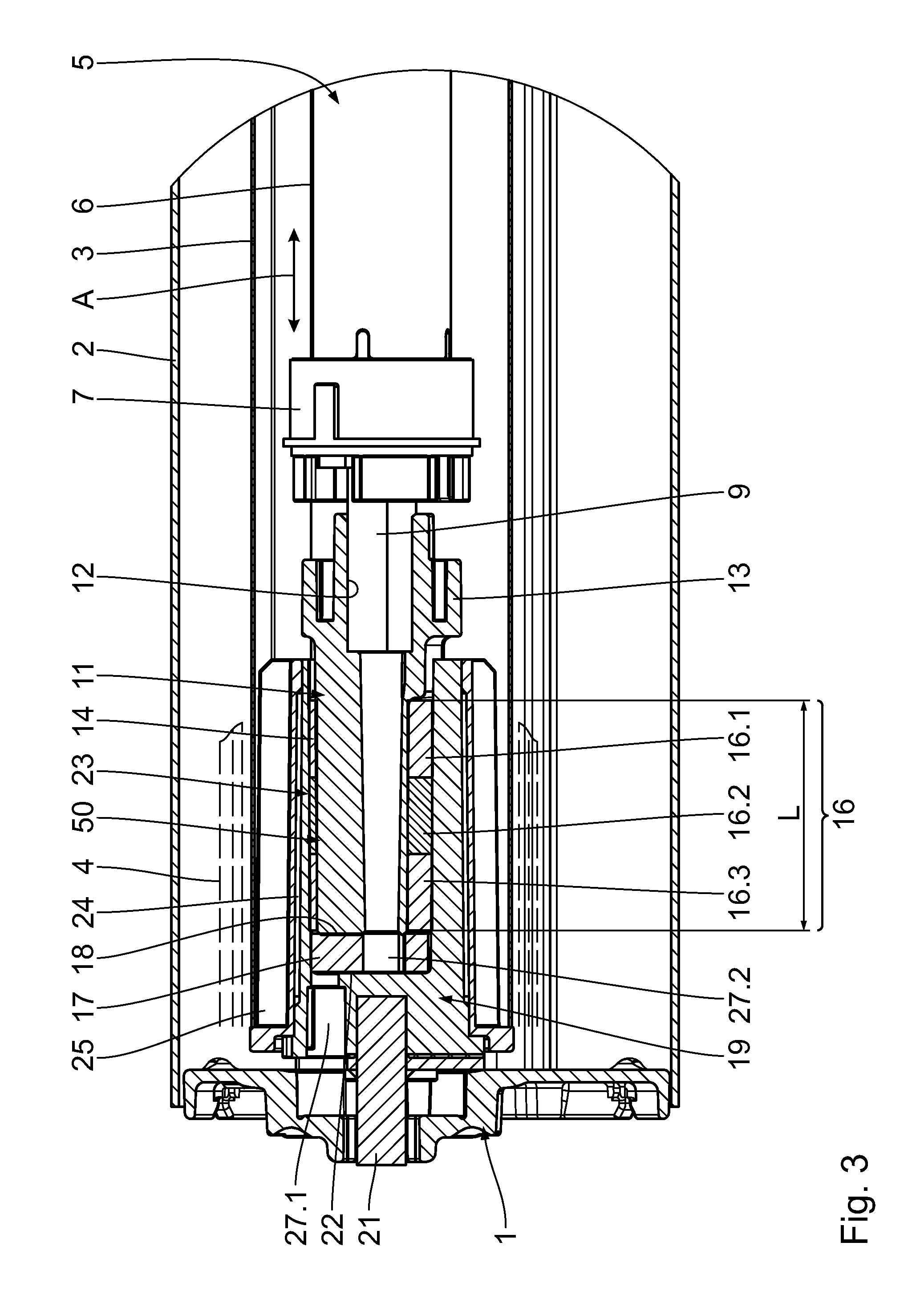
[0034]The awning is a housing awning in which the components are arranged in a housing 2. These components essentially include the tube-shaped fabric shaft 3 which is mounted between the holding bracket 1 shown in the Figures and the second holding bracket; the fabric shaft 3 is mounted for rotation on the holding brackets 1 in a way that is set out below. An awning fabric 4 which is shown dashed in FIG. 3 can be wound in and out by means of the fabric shaft 3. The extending and retracting movement of the awning fabric 4 is of no importance in the present invention; it can for example be performed using joint arms and a drop-out bar together with ...


PUM


Abstract

An awning comprisestwo holding brackets arranged on a base member between which a fabric shaft is mounted for rotation;an awning fabric which is windable in on or out on the fabric shaft; anda motor drive for rotating the fabric shaft, which motor drive is installed in the awning shaft and is mounted on one of the holding brackets in a vibration-damped manner, anda vibration insulation device which is completely arranged inside the fabric shaft between the motor drive and the holding bracket, the vibration insulation device comprisinga support head which secures the motor drive against rotation,a radial damping member of a vibration-damping, flexible material which positively engages the support head in the direction of rotation; anda mounting head which is non-rotatably mounted on the holding bracket and positively engages the radial damping member in the direction of rotation.

Description

CROSS-REFERENCES TO RELATED APPLICATIONS[0001]This application claims the priority of German Patent Application, Serial No. 10 2012 202 824.2, filed Feb. 24, 2012, pursuant to 35 U.S.C. 119(a)-(d), the content of which is incorporated herein by reference in its entirety as if fully set forth herein.SUMMARY OF THE INVENTION[0002]The invention relates to an awning comprising[0003]two holding brackets arranged on a base member between which a fabric shaft is mounted for rotation;[0004]an awning fabric which is windable on and off the fabric shaft; and[0005]a motor drive for rotating the fabric shaft, which motor drive is installed in the awning shaft and is mounted on one of the holding brackets in a vibration-damped manner.BACKGROUND OF THE INVENTION[0006]Awnings of this type have a basic design which has been known for a long time, comprising a base member mountable to a part of a building, two holding brackets arranged thereto, a fabric shaft mounted for rotation therebetween, an aw...

Claims


Application Information

Patent Timeline
Patent Type & Authority Applications(United States)
IPC IPC(8): E04F10/06
CPCE04F10/0644E04F10/0648
Inventor KRONER, SVEN
Owner SCHMITZ WERKE
Why Eureka
Try Eureka