Molding assembly with heating and cooling system

Inactive Publication Date: 2013-08-29
FORD MOTOR CO
View PDF3 Cites 28 Cited by
  • Summary
  • Abstract
  • Description
  • Claims
  • Application Information

AI Technical Summary

Benefits of technology

[0004]According to one aspect of the present invention, a molding assembly for making molded parts includes a molding tool having conformal fluid lines that follow contours of a molding surface of the molding tool. The conformal fluid lines are defined in the

Problems solved by technology

Heating and cooling the molding the co

Method used


Image

  • Molding assembly with heating and cooling system
  • Molding assembly with heating and cooling system
  • Molding assembly with heating and cooling system

Examples


Embodiment Construction

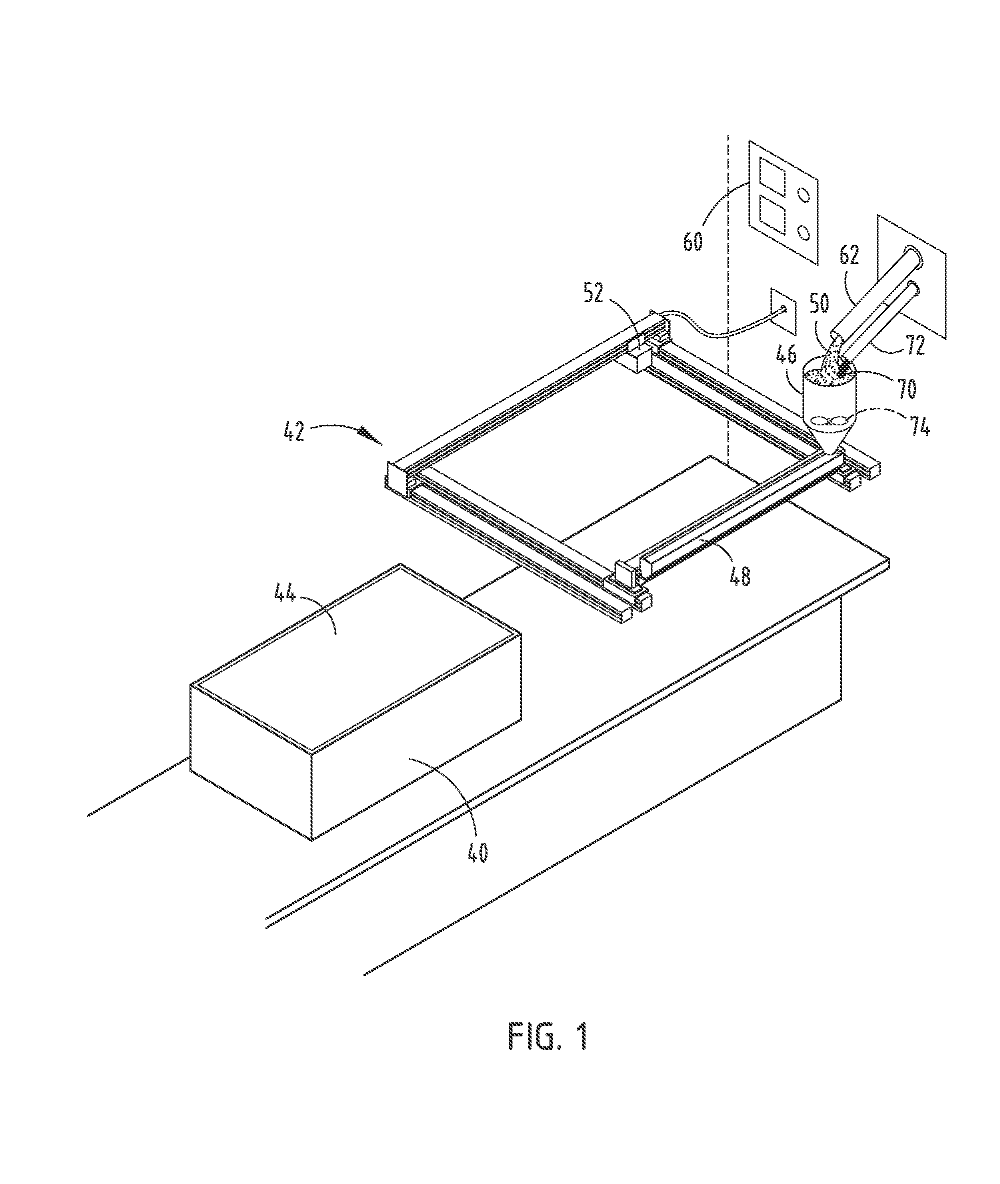
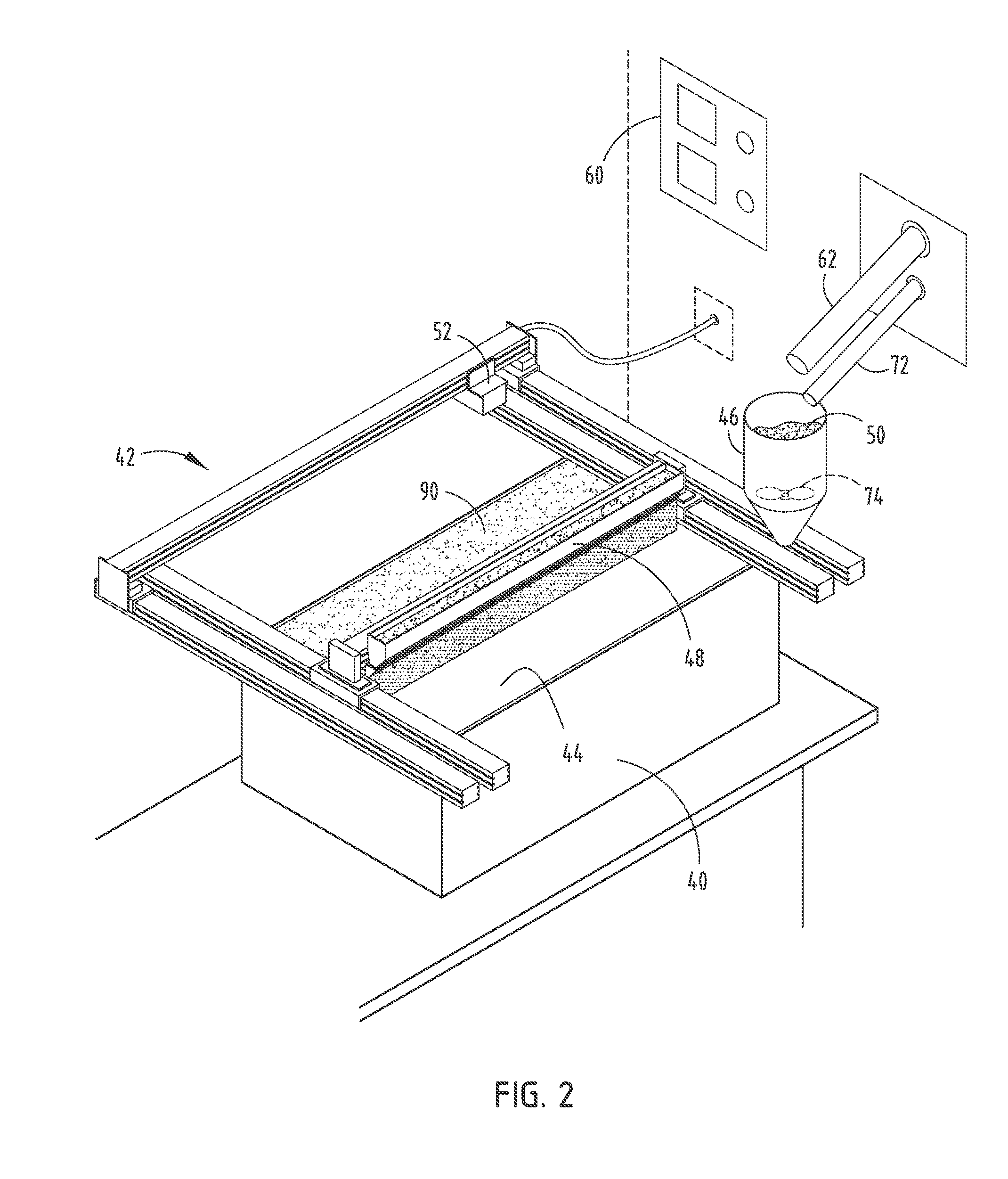
[0061]For purposes of description herein, the terms “upper,”“lower,”“right,”“left,”“rear,”“front,”“vertical,”“horizontal,” and derivatives thereof shall relate to the invention as oriented in FIG. 1. However, it is to be understood that the invention may assume various alternative orientations, except where expressly specified to the contrary. It is also to be understood that the specific devices and processes illustrated in the attached drawings, and described in the following specification are simply exemplary embodiments of the inventive concepts defined in the appended claims. Hence, specific dimensions and other physical characteristics relating to the embodiments disclosed herein are not to be considered as limiting, unless the claims expressly state otherwise.

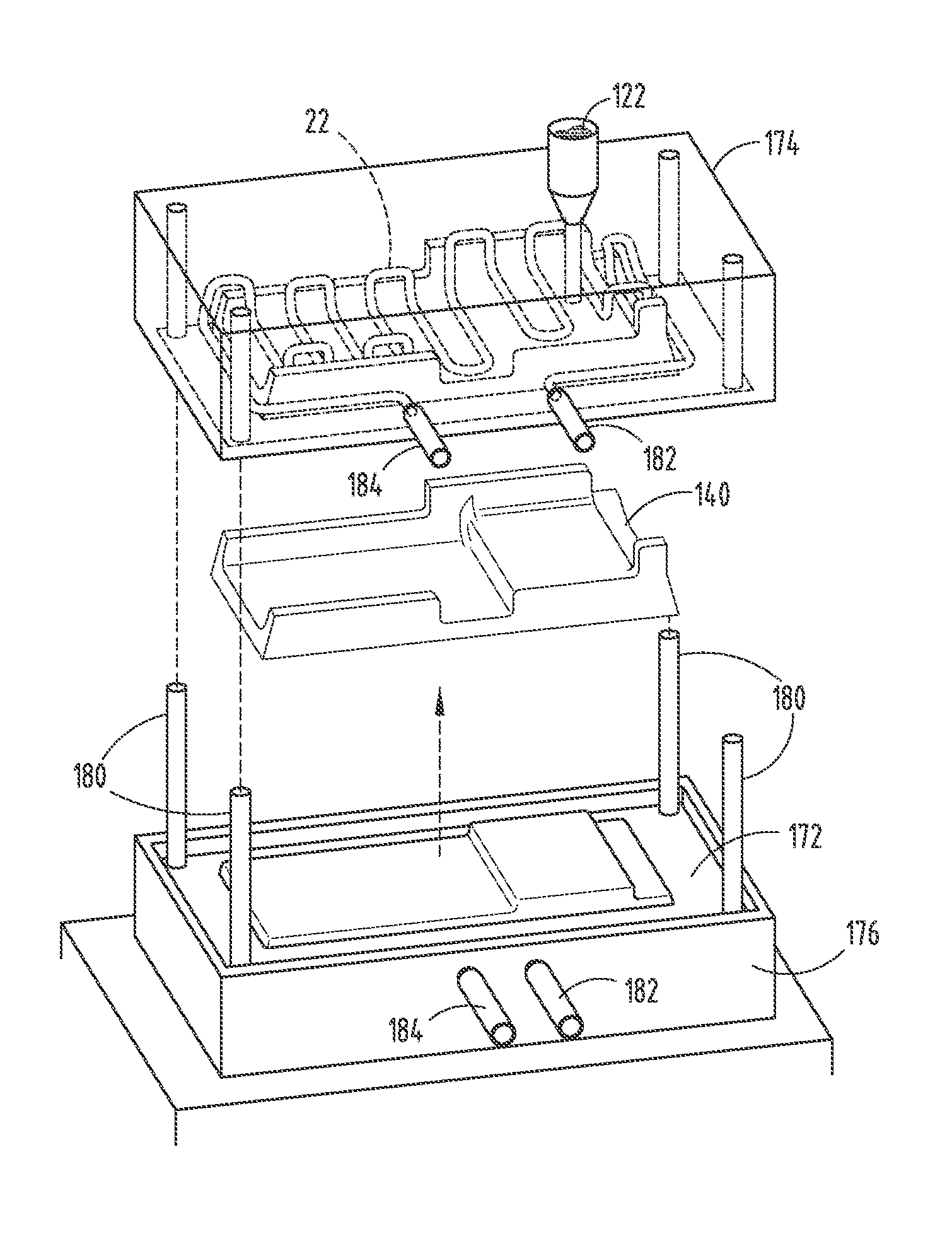
[0062]Referring to FIGS. 1-27, a mold core package 10 is illustrated. The mold core package 10 is used to form a molding tool 12. The mold core package 10 includes a plurality of stacked particulate layers 14 having a bi...


PUM

PropertyMeasurementUnit
Temperatureaaaaaaaaaa
Flow rateaaaaaaaaaa
Moldableaaaaaaaaaa

Abstract

A molding assembly for making molded parts includes a molding tool having conformal fluid lines that follow contours of a molding surface of the molding tool. The conformal fluid lines are defined in the molding tool during casting by sacrificial displacement lines formed by a three-dimensional printer. A temperature control station is coupled to the molding tool and includes a heating and cooling fluid. A valve station regulates fluid flow to the molding tool.

Description

CROSS-REFERENCE TO RELATED APPLICATIONS[0001]This application is related to the following applications: U.S. patent application Ser. No. ______, filed on Feb. 29, 2012, entitled “MOLD CORE FOR FORMING A MOLDING TOOL” (Atty. Docket No. 83203377); U.S. patent application Ser. No. filed on Feb. 29, 2012, entitled “INTERCHANGEABLE MOLD INSERTS” (Atty. Docket No. 83203382); U.S. patent application Ser. No. ______, filed on Feb. 29, 2012, entitled “MOLD CORE PACKAGE FOR FORMING A POWDER SLUSH MOLDING TOOL” (Atty. Docket No. 83225801); U.S. patent application Ser. No. ______, entitled “MOLDING TOOL WITH CONFORMAL PORTIONS AND METHOD OF MAKING THE SAME” (Atty. Docket No. 83225806); and U.S. patent application No. Ser. ______, filed on Feb. 29, 2012, entitled “ADDITIVE FABRICATION TECHNOLOGIES FOR CREATING MOLDS FOR DIE COMPONENTS” (Atty. Docket No. 83225814), the entire disclosures of which are hereby incorporated herein by reference.FIELD OF THE INVENTION[0002]The present invention general...

Claims


Application Information

Patent Timeline
IPC IPC(8): B22C9/02B22D27/04
CPCB22C9/02B22C23/00B29C33/04B29C45/73B22F2003/1058B22C13/085B22F5/007B22C9/065B22C9/10B22C9/12B22F3/1055B33Y80/00Y02P10/25B22F10/14B22F10/47B21D37/16B22C9/06B21J13/02
Inventor ROCCO, CHARLES ALANKALISZ, RAYMOND EDWARDCONLEY, JEFFERY N.MARCHETTI, BERNIE GERARD
Owner FORD MOTOR CO
Why Eureka
Try Eureka