Method and System for Calculating Total Received Power of High Speed Physical Downlink Shared Channel

a technology of shared channel and total received power, applied in the field of wireless communication system, can solve problems such as call drop in the terminal

Active Publication Date: 2013-08-29
XIAN ZHONGXING NEW SOFTWARE
View PDF4 Cites 21 Cited by
  • Summary
  • Abstract
  • Description
  • Claims
  • Application Information

AI Technical Summary

Benefits of technology

[0034]With the method and system of the example, when the terminal prepares to perform a serving HS-DSCH cell handover across an IUR interface, the serving radio network controller of the terminal can obtain the information of the measured power deviation of the target serving HS-DSCH cell, thereby configuring the correct information of the measured power...

Problems solved by technology

The problem of call dro...

Method used


Image

  • Method and System for Calculating Total Received Power of High Speed Physical Downlink Shared Channel
  • Method and System for Calculating Total Received Power of High Speed Physical Downlink Shared Channel
  • Method and System for Calculating Total Received Power of High Speed Physical Downlink Shared Channel

Examples


example 1

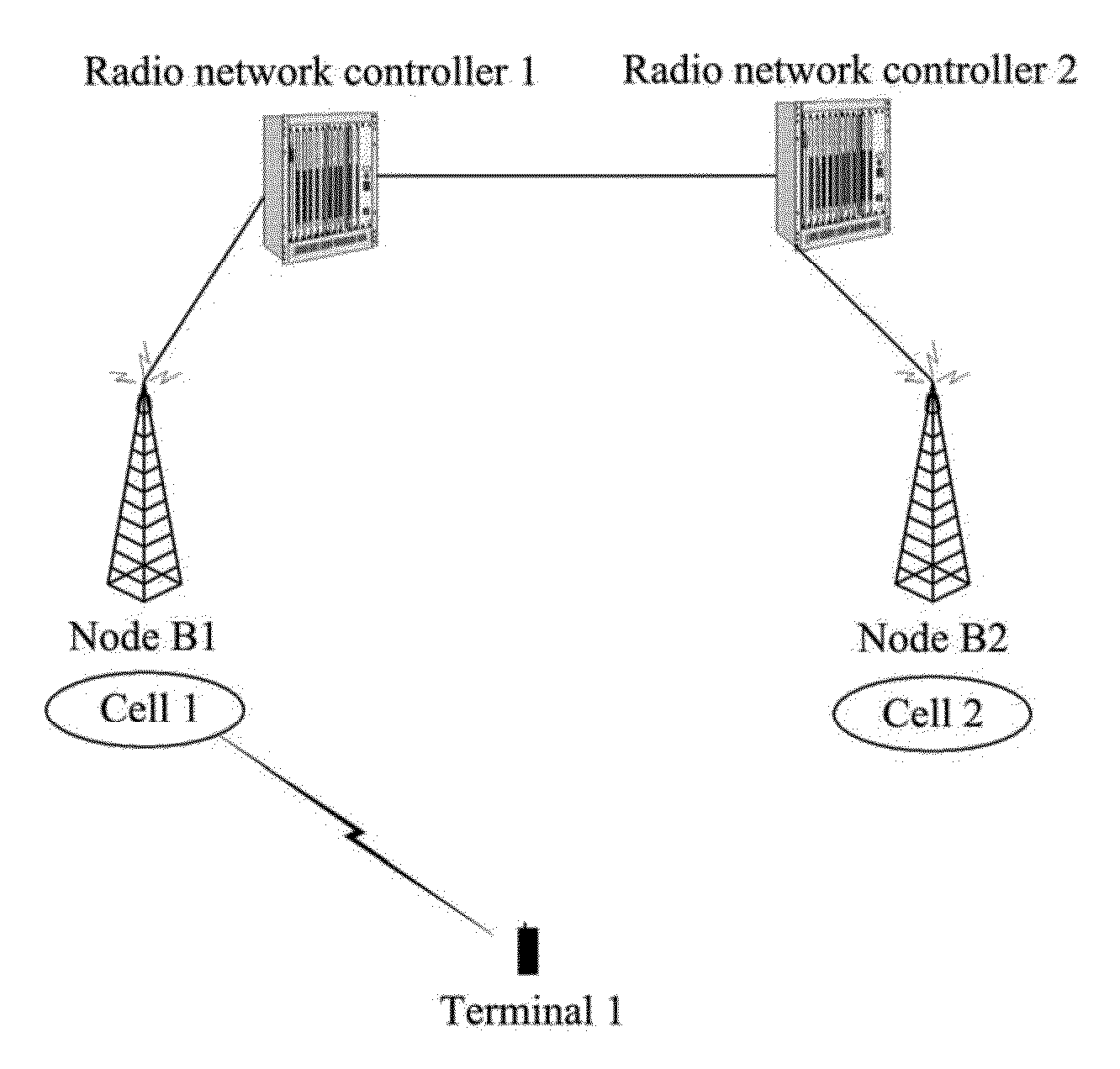
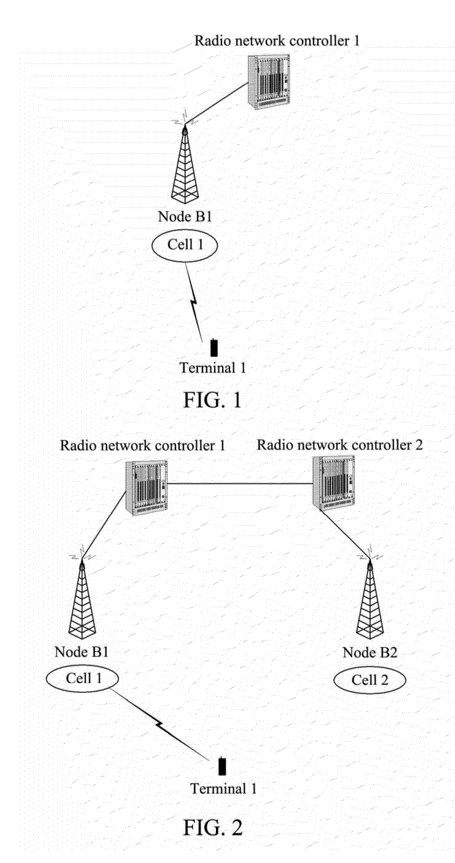
[0048]A single-carrier setting scenario of the present example is a scenario shown in FIG. 2 (that is the scenario mentioned in the background of the related art): a controlling radio network controller of a cell 1 is a radio network controller 1, and a controlling radio network controller of a cell 2 is a radio network controller 2. An IUR interface exists between the radio network controller 1 and the radio network controller 2. A terminal 1 uses the high speed downlink packet access technology to transmit and receive the service data in the cell 1. The terminal 1 moves from the cell 1 to the cell 2, the radio network controller 1 is a serving radio network controller of the terminal 1, and the radio network controller 2 is a drift radio network controller of the terminal 1. The terminal 1 moves from the cell 1 to the cell 2, the cell 1 and the cell 2 are co-channel cells, the cell 1 is a current serving HS-DSCH cell of the terminal 1, and the cell 2 is a target serving HS-DSCH ce...

example 2

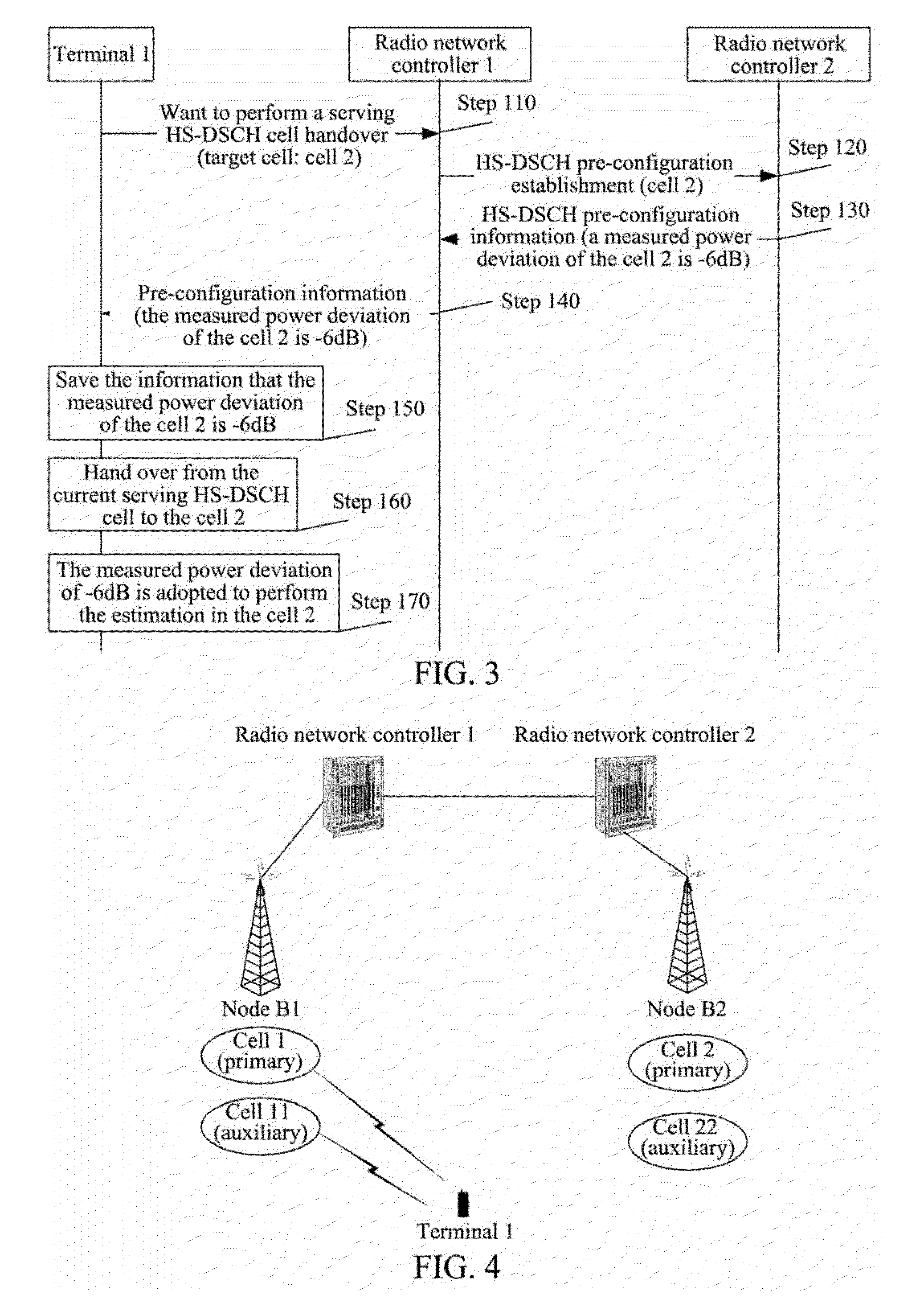
[0059]A multi-carrier setting scenario of the example is as shown in FIG. 4. Since one cell has one and only one carrier, when using the multi-carrier high speed packet access technology, at least two cells must be required, wherein a carrier of one cell serves as a primary carrier, and a carrier of the other cell serves as an auxiliary carrier. Such two cells are called as Dual-cell. The multi-carrier setting scenario is a scenario as shown in FIG. 4, wherein a controlling radio network controller for a cell 1 and a cell 11 is a radio network controller 1, and a controlling radio network controller for a cell 2 and a cell 22 is a radio network controller 2. An IUR interface exists between the radio network controller 1 and the radio network controller 2. The cell 1 and the cell 2 are co-channel cells, and the cell 11 and the cell 22 are co-channel cells. The cell 1 and the cell 11 constitute a dual-cell. The cell 2 and the cell 22 constitute a dual-cell. The terminal 1 uses the hig...

example 3

[0072]A system for implementing the above method described in the patent document includes a serving radio network controller and a drift radio network controller, wherein the serving radio network controller includes a first module and a second module, wherein:

[0073]the first module of the serving radio network controller is configured to: when a terminal performs a serving HS-DSCH cell handover across an IUR interface, request the drift radio network controller to establish an HS-DSCH pre-configuration in a target serving HS-DSCH cell dominated by the drift radio network controller;

[0074]the drift radio network controller is configured to return information of a measured power deviation of the target serving HS-DSCH cell which serves as HS-DSCH pre-configuration information to the serving radio network controller; and

[0075]the second module of the serving radio network controller is configured to take the information of the measured power deviation of the target serving HS-DSCH ce...


PUM


Abstract

A method for calculating total received power of an HS-PDSCH is disclosed in the patent document, comprising: when a terminal performs an HS-DSCH cell handover across an IUR interface, an SRNC requesting a DRNC to establish an HS-DSCH pre-configuration; the DRNC returning information of a measured power deviation of a target serving cell to the SRNC; the SRNC sending said information to the terminal; and after performing the handover to the target serving cell, the terminal using the measured power deviation of the target serving cell to estimate the total received power of the HS-PDSCH in the target serving cell. A system for calculating the total received power of the HS-PDSCH is also disclosed in the patent document, and the system comprises: a first module and second module of a serving radio network controller, a drift radio network controller and a terminal.

Description

TECHNICAL FIELD[0001]The patent document relates to the wireless communication system, and specifically, to a method and system for calculating total received power of a high speed physical downlink shared channel using the high speed downlink packet access technology in the third generation wireless communication system.BACKGROUND OF THE RELATED ART[0002]The high speed downlink packet access technology introduces a new transmission channel namely a High Speed Downlink Shared Channel (HS-DSCH), which is used for bearing the actual user data accessed by the high speed downlink packet. The high speed packet access technology introduces new physical channels. A High Speed Shared Control Channel (HS-SCCH) is one of the newly added physical channels and is used for bearing certain important control signaling information. The working process of HS-DSCH is always accompanied by the HS-SCCH.[0003]In the high speed downlink packet access technology, in all cells in a soft handover active set...

Claims


Application Information

Patent Timeline
IPC IPC(8): H04W24/04
CPCH04W24/10H04W28/04H04W36/10H04W36/0072H04W24/04
Inventor CHENG, XIANG
Owner XIAN ZHONGXING NEW SOFTWARE
Why Eureka
Try Eureka