
Method and Device for Determining a Quality of a Clock Signal

a clock signal and quality technology, applied in the direction of transmission monitoring, line-transmission details, multiplex communication, etc., can solve the problems of not being able to detect sudden external disturbances applied to the synchronization hardware, and conventional solutions cannot determine the quality of the controlled time valu

Inactive Publication Date: 2013-08-29
SIEMENS AG
View PDF1 Cites 7 Cited by
  • Summary
  • Abstract
  • Description
  • Claims
  • Application Information

AI Technical Summary

Benefits of technology

The invention aims to improve the accuracy of timing in a network of devices. It allows a slave device to determine the quality of a controlled time signal and detect sudden disturbances caused by mechanical impact. The invention also adjusts the communication interval based on the quality of the clock signal, which helps in packing communication time slots of different clients sharing one network more densely without causing interference. Ultimately, a good synchronization allows for shorter time slots used for communication purposes, increasing available bandwidth and overall performance of the system.

Problems solved by technology

However, conventional solutions are neither able to determine the quality of the value of the controlled time nor to detect sudden external disturbances applied to the synchronization hardware, such as vibrations or shocks.

Method used


Image

  • Method and Device for Determining a Quality of a Clock Signal
  • Method and Device for Determining a Quality of a Clock Signal
  • Method and Device for Determining a Quality of a Clock Signal

Examples


Embodiment Construction

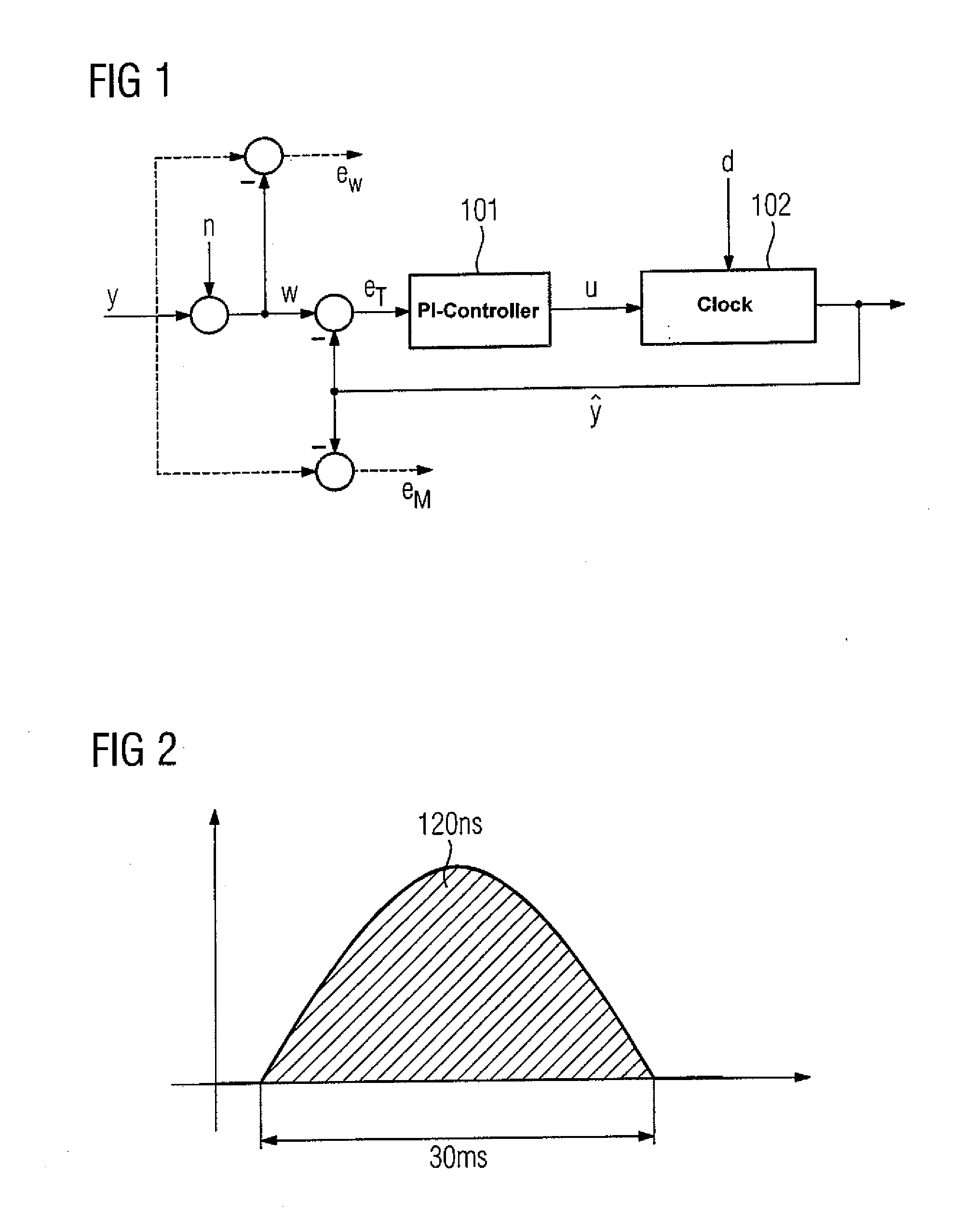
[0044]FIG. 1 shows a structure of a clock synchronization control loop that may be implemented in a slave device. When the clock of the slave device is not (significantly) disturbed by external disturbances (e.g. shocks or vibrations), the only relevant disturbance for the clock synchronization process is a signal n by which an estimated master time w differs from a true master time y. It is noted that the disturbance n comprises all noise and disturbances between the master and this actual slave device (cumulated noise).

[0045]An error eT denotes a tracking error that is input to a PI-controller 101 (i.e., a controller comprising a proportional (P) and an integral (I) portion). The output of the PI-controller 101 comprises a signal u that is fed to a controlled clock 102 of the slave device. The output of the controlled clock 102 is denoted as a controlled time ŷ, which is subtracted from the estimated master time w.

[0046]The controlled clock 102 may be subject to disturbances d (e....


PUM


Abstract

Method, device and system for detecting a disturbance, e.g., at least one short mechanical impact (shock or vibration) on a clock of a slave device by detecting a non-typical variation of a tracking error, i.e., a tracking error having a deviation that exceeds a predetermined threshold, wherein such a non-typical variation can be determined by the deviation from a statistical measure, e.g., a variance or a standard deviation, such that the determination of the quality of a clock signal is advantageously allowed and thus suitable counter-measures are provided. The method, device and system are applicable for all kinds of technical systems comprising slave devices that have a clock, e.g., devices in industrial and automation systems. The method, device and system are also applicable in communication systems that use a protocol to synchronize the clocks of its devices, e.g., Profinet.

Description

BACKGROUND OF THE INVENTION[0001]1. Field of the Invention[0002]The present invention relates to a method and device for determining a quality of a clock signal in a slave device.[0003]2. Description of the Related Art[0004]Clock synchronization is a basis for proper operation of process automation and control systems. Typically, each element of an automation system (i.e., a slave device) has an internal clock (driven by a quartz) which has to be synchronized with the clock of an (a priori selected) master device.[0005]Profinet-based systems use a given protocol (based, among others, on the Institute of Electrical and Electronic Engineers (IEEE) standard 1588-2008) to enable synchronization. Here, the synchronization is based on sequentially transmitting SYNC-messages from one element to the next in a chain structure. Locally at the slave device, a control algorithm is used to generate a smooth version of the master time estimate, which is called “controlled time”, and is the output...

Claims


Application Information

Patent Timeline
Patent Type & Authority Applications(United States)
IPC IPC(8): H04L1/20
CPCH04J3/0638H04L1/20H04L1/205H04J3/14
Inventor BUHL, MICHAEL BERNHARDOBRADOVIC, DRAGANSTEINDL, GUNTERWOLFRUM, PHILIPP
Owner SIEMENS AG
Learn More