Image processing method and device, and program

a technology of image processing and image quality, applied in the field of image processing methods and devices, can solve the problems of low image quality and low precision of the completed combined image, and achieve the effect of high quality and high precision

Active Publication Date: 2013-08-29
CANON KK
View PDF4 Cites 199 Cited by
  • Summary
  • Abstract
  • Description
  • Claims
  • Application Information

AI Technical Summary

Benefits of technology

[0013]According to the present invention, in the image processing of multi-viewpoint image data including image data captured with different focal lengths, it is mad

Problems solved by technology

In this case, the image data captured by a single camerawith a different angle of view is not utilized, and therefore, the combined image that is completed is of relatively low image quality.
Similarly, also in the case where a distance to a subject is

Method used


Image

  • Image processing method and device, and program
  • Image processing method and device, and program
  • Image processing method and device, and program

Examples


first embodiment

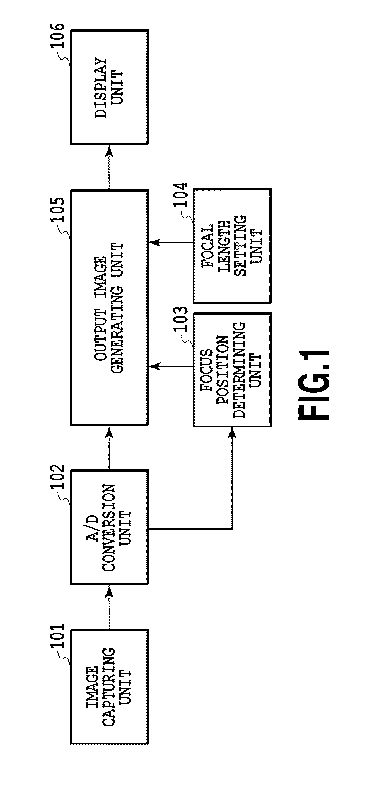
[0045]FIG. 1 is a diagram showing essential components of an image capturing device according to a first embodiment.

[0046]An image capturing unit 101 includes a zoom lens, focus lens, camera-shake correction lens, stop, shutter, optical low-pass filter, IR cut filter, color filter, and image sensing elements (sensor), such as CMOS and CCD, and is configured to detect an amount of light of a subject. Note that, the image capturing unit 101 in the present embodiment is a camera array with different focal lengths which is capable of simultaneously capturing a plurality of images from different viewpoints and in which a plurality of single cameras having two or more kinds of focal lengths exists mixedly.

[0047]An A / D conversion unit 102 converts an amount of light of a subject detected by the image capturing unit 101 into a digital value and sends a digital signal (digital image data) to an output image generating unit 105.

[0048]A focus position determining unit 103 determines a focus po...

second embodiment

[0128]In the first embodiment, the aspect is explained, in which image combination is performed using only the image data captured by the single cameras with a focal length equal to or less than the output focal length. Next, an aspect is explained as a second embodiment, in which image combination is performed using image data captured by all the single cameras regardless of the length of the output focal length. Explanation of parts common to those of the first embodiment is simplified or omitted and here, different points are explained mainly.

[0129]In the present embodiment, in the use image manipulation processing at step 505 of the flowchart of FIG. 5, regardless of the output focal length that is set, resolution conversion in accordance with necessity is performed on image data captured by all the single cameras configuring the camera array with different focal lengths.

[0130]FIG. 20 is a diagram for explaining the way of resolution conversion in the present embodiment.

[0131]A ...

third embodiment

[0134]Next, an aspect is explained as a third embodiment, in which a filter is applied to each image to further reduce a blur. Explanation of parts common to those of the first and second embodiments is simplified or omitted and here, different points are explained mainly.

[0135]FIG. 22 is a diagram showing an example of an internal configuration of an output image generating unit 2200 according to the present embodiment. In comparison with the output image generating unit 105 according to the first embodiment (see FIG. 3), it is known that a filter applying unit 2201 is added to the output image generating unit 2200 according to the present embodiment.

[0136](Filter Applying Unit)

[0137]FIG. 23 is a diagram showing an example of an internal configuration of the filter applying unit 2201.

[0138]The filter applying unit 2201 includes an image buffer 2301, a filter diameter deriving unit 2302, an application determining unit 2303, a coefficient deriving unit 2304, and an arithmetic operat...


PUM


Abstract

In image processing of multi-viewpoint image data including image data captured with different focal lengths, an image of high quality, distance information with high precision, etc., are obtained by utilizing image data with different angles of view (focal lengths). An image processing device for generating combined image data using multi-viewpoint image data including image data acquired with different focal lengths, includes a resolution converting unit configured to perform resolution conversion for at least part of image data in multi-viewpoint image data in accordance with a focal length to be output and an image combining unit configured to generate combined image data with the focal length to be output using the resolution-converted image data.

Description

BACKGROUND OF THE INVENTION[0001]1. Field of the Invention[0002]The present invention relates to combination processing of an image using multi-viewpoint image data.[0003]2. Description of the Related Art[0004]Conventionally, when an image was captured by a camera out of focus, it was necessary to recapture the image after performing focusing again. Further, when it was desired to obtain focused images of a plurality of subjects with different depths, it was necessary to capture the image of each subject in focus a plurality of times.[0005]In recent years, a technique called light field photography has been developed, which is capable of adjusting the focus position in the later image processing (refocus) by adding a new optical element to the optical system to acquire images from multiple viewpoints.[0006]By using this technique, there is an advantage that a failure in focusing at the time of image capturing can be made up by image processing because it is possible to perform focus...

Claims


Application Information

Patent Timeline
IPC IPC(8): G06K9/36
CPCG06T5/50G06K9/36H04N5/23232G06T2207/20221G06T2207/10052G06T2207/10148H04N13/0242H04N13/243H04N23/951
Inventor NISHIYAMA, TOMOHIRO
Owner CANON KK
Why Eureka
Try Eureka