Chain transmission

a chain transmission and chain technology, applied in the direction of driving chains, belts/chains/gearrings, driving chains, etc., can solve the problems of impaired chain transmission efficiency, reduce the space occupied by the guide in the chain transmission, reduce the sound of sliding contact, and reduce the size of the chain guid

Inactive Publication Date: 2013-08-29
TSUBAKIMOTO CHAIN CO
View PDF7 Cites 9 Cited by
  • Summary
  • Abstract
  • Description
  • Claims
  • Application Information

AI Technical Summary

Benefits of technology

[0013]With the interposition of the chain guide between the outer plates, the chain is restricted by engagement of the inward-facing surfaces of the outer plates with the outer plate-engaging surfaces of the guide, and meandering of the chain, and jumping of the chain out of engagement with the chain guide, can be more effectively suppressed.
[0014]Because the chain guide does not need to be wider than the chain, the size of the chain guide can be reduced, and the space occupied by the guide in a chain transmission can be reduced accordingly. Furthermore, because the range in which the transmission chain can meander is restricted to a distance corresponding to the widths of the small gaps between the inner side surfaces of the outer plates and the outwardly facing, outer plate-engaging surfaces of the guide, it is possible to reduce sliding contact sounds generated by meandering of the chain, and also to reduce frictional losses.
[0015]According to a third aspect of the invention, the chain guide can also include a pair of outer plate-engaging surfaces facing in the chain height direction, extending in parallel to the inner plate-engaging surface, and in sliding engagement with edges of outer plates of the chain. In this case it becomes possible to reduce the surface pressure applied by the chain to the chain guide, and thereby reduce wear of the chain guide.
[0016]According to a fourth aspect of the invention, the outer plates can be held on the connecting pins by caulked end portions of the connecting pins. Thus, the end portions of a pin can be engaged with opposed outer plates around the entire periphery of the pin. Consequently, the number of parts of the chain, and the overall weight of the chain, can be reduced.
[0017]According to a fifth aspect of the invention, the outer plates can be held on the connecting pins by stop rings press-fit onto end portions of the connecting pins. The stop rings can securely prevent the outer plates from becoming disconnected from the connecting pins.

Problems solved by technology

The efficiency of the chain transmission is also impaired by excessive friction due to contact between the inner link plates 514 and the chain guide.

Method used


Image

  • Chain transmission
  • Chain transmission
  • Chain transmission

Examples


Embodiment Construction

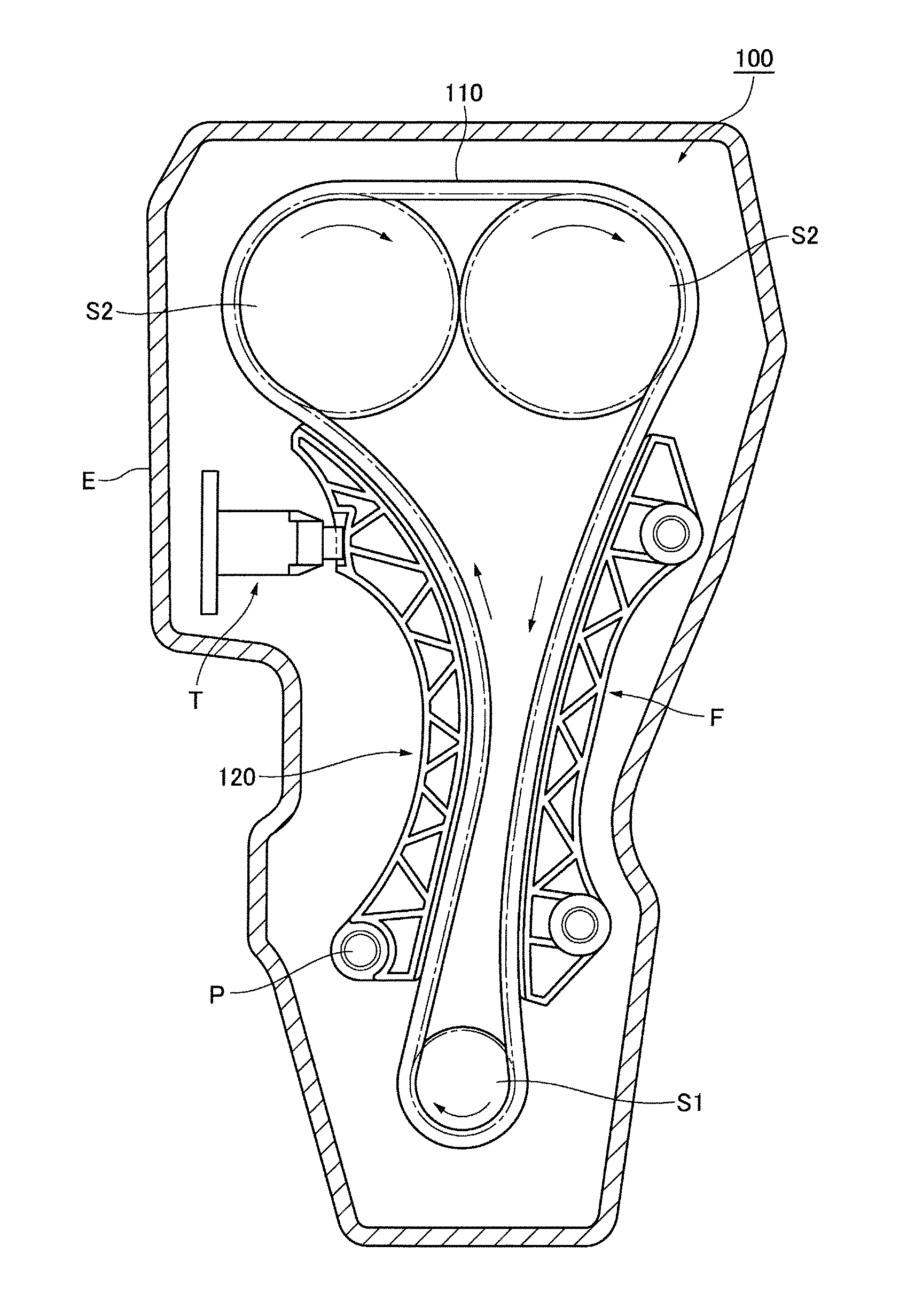
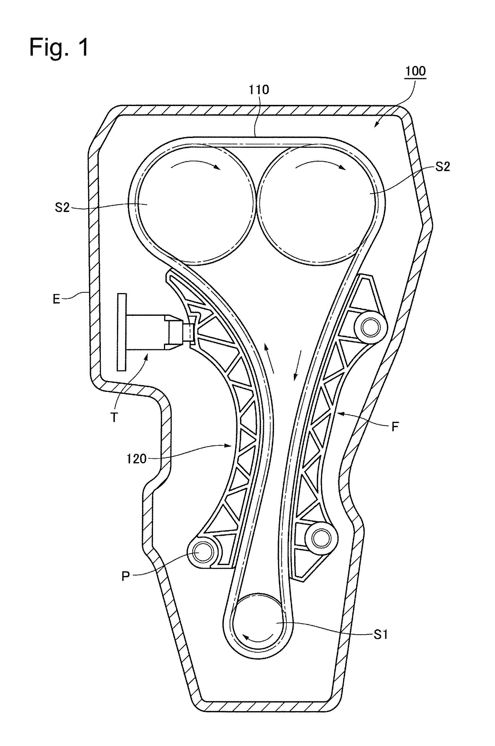
[0033]The chain transmission 100 shown in FIG. 1 is a timing chain transmission of an dual overhead valve (DOHC) automobile engine, used to transmit power from the engine crankshaft to a pair of valve-operating camshafts.

[0034]The chain transmission 100 comprises a chain 110, a movable guide 120 on which the chain slides in a longitudinal direction, a fixed chain guide F, a chain-driving sprocket S1 on the engine crankshaft (not shown), and two driven sprockets S2 on the engine camshafts (not shown).

[0035]The movable guide 120 described above is pivotably mounted on the block of an engine E by a shoulder bolt P, and is urged against the span of the chain that travels from the crankshaft sprocket S1 toward a camshaft sprocket S2 by the plunger of a tensioner T, which maintains proper tension in the transmission chain 110 in order to prevent failure caused by excessive tension or excessive slack in the chain.

[0036]The fixed guide F is in sliding engagement with an opposite span of the...


PUM


Abstract

A transmission chain is composed of pairs of outer plates and pairs of inner plates. The plates of each pair are in opposed, spaced relation to each other. The pairs of inner plates and the pairs of outer plates are disposed in alternating, overlapping, relationship along the length of the chain, with each pair of inner plates extending in a first direction into a space between one pair of outer plates, and in a second direction, opposite to the first direction, into a space between another pair of outer plates. Connecting pins connect the alternating pairs of plates in articulating relationship. Each of the connecting pins is press-fit into holes in a pair of inner plates and fits rotatably in holes in a pair of outer plates. A guide extends into a space between the outer plates, guiding the chain by engagement with inwardly facing surfaces of the outer plates.

Description

CROSS REFERENCE TO RELATED APPLICATIONS[0001]The disclosure of Japanese Patent Application No. 2012-037855, filed on Feb. 23, 2012, is here incorporated by reference.FIELD OF THE INVENTION[0002]This invention relates to a chain transmission comprising a chain for transmitting power from one or more driving sprockets to one or more driven sprockets, and one or more guides on which the chain slides.BACKGROUND OF THE INVENTION[0003]FIGS. 13 and 14 show a prior art chain transmission 500, comprising a roller chain 510 and a chain guide 520 on which the chain slides. Sprockets (not shown) are in driving and driven engagement with the chain. The chain 510 has outer links 513, each composed of a pair of right and left outer link plates 511 and connecting pins 512 press-fit into pin holes 511a of the outer links. The chain also has inner links 516, each composed of a pair of right and left inner link plates 514, and bushings 515 press-fit into bushing holes 514a in the inner link plates 514...

Claims


Application Information

Patent Timeline
Patent Type & Authority Applications(United States)
IPC IPC(8): F16H7/18
CPCF16H7/18F16G13/06
Inventor YOKOYAMA, MASANORI
Owner TSUBAKIMOTO CHAIN CO
Why Eureka
Try Eureka