Method for Presenting the Drift Values of an Aircraft

a technology for aircraft and drift vectors, applied in position/direction control, traffic control systems, reradiation, etc., can solve the problem of physical limitation of display devices, pilots no longer being able to optically resolve the length, and restricting hardware representational length of drift vectors

Inactive Publication Date: 2013-08-29
AIRBUS DEFENCE & SPACE
View PDF5 Cites 9 Cited by
  • Summary
  • Abstract
  • Description
  • Claims
  • Application Information

AI Technical Summary

Benefits of technology

[0005]Exemplary embodiments of the present invention provide a method for representing the drift vector that produces a representation the pilot can easily detect even small drift values without the need to reduce the quality of the representation at higher drift values.
[0008]The inventive method provides good visibility of the drift vector over the entire value range to be represented and, particularly in the case of small drift values. In particular, there is no need for a manual switching over between different resolutions of the display, or for the use of a plurality of display devices. It is therefore possible to make a substantial contribution to a risk-free, safe landing.

Problems solved by technology

The problem that results therefrom for the above-described, proportional representation is that the HMI of the drift display must, on the one hand, represent the smallest lateral drifts during landing in a clearly detectable fashion, since these are classified as highly critical from the point of view of flight permission (the critical maximum value of the lateral drift is, for instance, 0.4 kts for a type CH53 helicopter), and, on the other hand, the display resolution of the display device is physically limited, and this restricts the representational length of the drift vector in terms of hardware.
It is apparent that the pilot is no longer able to optically resolve the length and, in some cases, also the direction of the drift vector in the case of small drift values such as occur typically during landing in a reliable way on the display.

Method used


Image

  • Method for Presenting the Drift Values of an Aircraft
  • Method for Presenting the Drift Values of an Aircraft
  • Method for Presenting the Drift Values of an Aircraft

Examples


Embodiment Construction

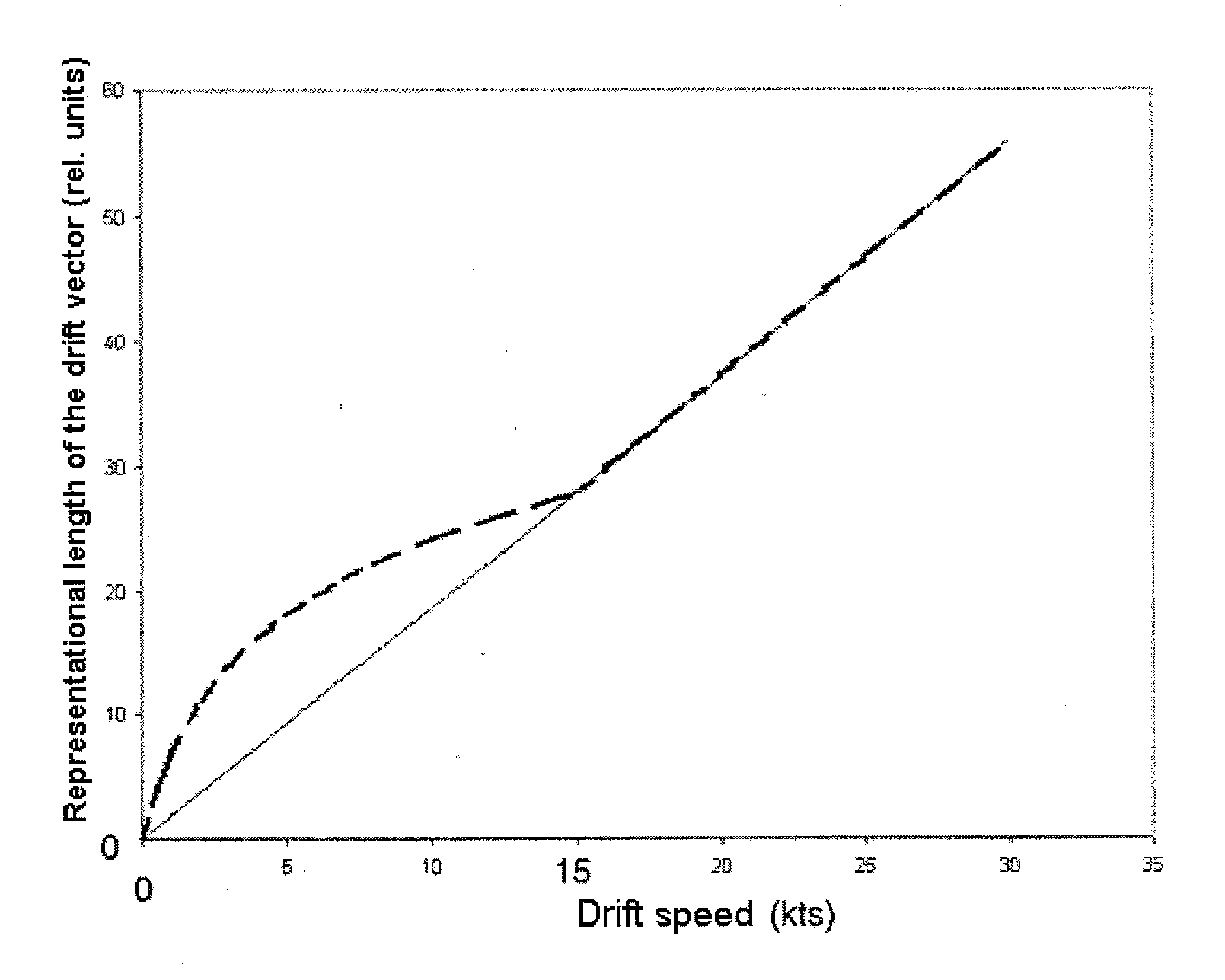
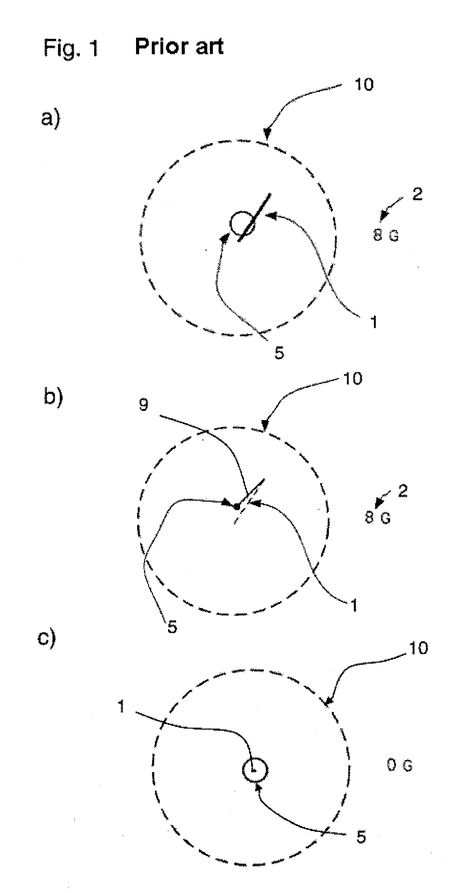
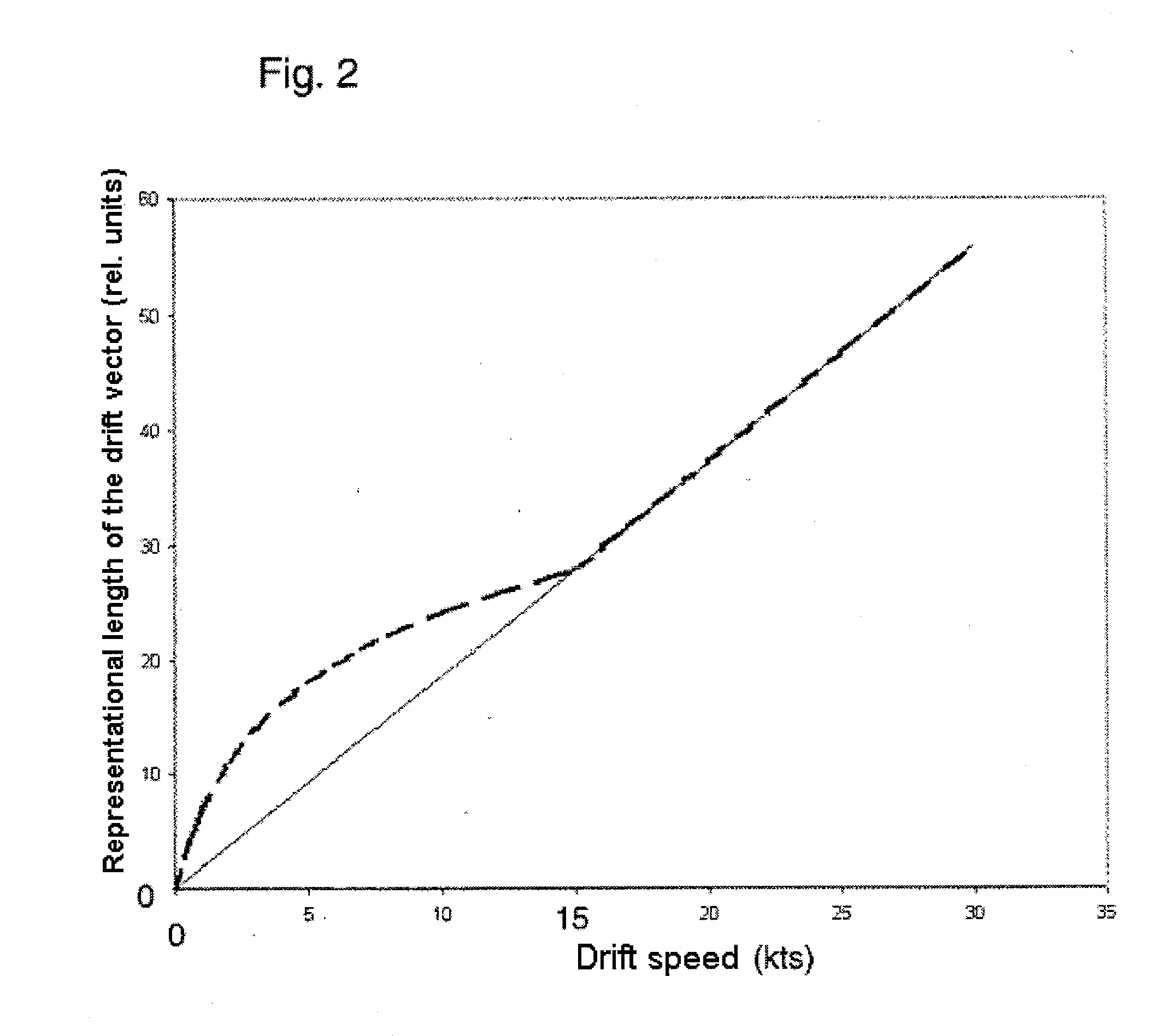
[0014]FIG. 1a shows a schematic representation of the drift vector in accordance with the prior art. The drift of the helicopter above ground is represented with the aid of a drift vector 1. The length specifies the absolute value of the speed above ground. The direction of the vector 1 specifies the direction of the drift above ground in relation to the helicopter longitudinal axis (typically an upward deflection of the vector represents a forward drift here). The reference circle 10 allows for the judgment of the relative length of the velocity vector 1 and corresponds in this example to a drift speed of 15 kts. It can also be taken only implicitly as a boundary of the display range and is not depicted in this case.

[0015]In addition, modern sensor-assisted landing aids are able to display a predicted value of the drift (acceleration cue), designed in FIGS. 1a and 1c in the form of a circle 5 whose center specifies where the tip of the drift vector 1 is located in a fixed time diff...


PUM


Abstract

A method for presenting the current drift values of an aircraft on a display device in which the drift values are presented in a vector presentation. The length of the drift vector above a predefined threshold value is presented in a manner proportional to the current drift velocity, and the length of the drift vector below the threshold value is presented in a manner disproportionate to the current drift velocity. There is a continuous transition between the two ways of presentation at the threshold value.

Description

BACKGROUND AND SUMMARY OF THE INVENTION[0001]Exemplary embodiments of the present invention relate to a method for representing the drift values of an aircraft with the drift values being represented in a vector representation.[0002]During a non-autonomous, sensor-assisted helicopter landing in restricted viewing conditions, for example brownout or whiteout conditions, the pilot must be presented with an easily detectable, unique representation of the drift direction and drift speed of the helicopter above the ground. The implementation of such symbols in an HMI (Human-Machine Interface) is performed either on a head-down display (multifunctional display MFD), on a head-up display (HUD) or a helmet-mounted sight display (HMS / D). The common practice is to represent the drift velocity by a so-called drift vector (reference 1, FIG. 1), that is to say a line (with or without representation of the start point and endpoint) starting from a fixed endpoint (typically the center of the area ...

Claims


Application Information

Patent Timeline
Patent Type & Authority Applications(United States)
IPC IPC(8): G01C23/00
CPCG01C23/005G01C23/00G08G5/0095G02B27/01G01S13/92
Inventor MUENSTERER, THOMAS
Owner AIRBUS DEFENCE & SPACE
Why Eureka
Try Eureka