Liquid crystal display device, display apparatus, and gate signal line driving method

a display device and display device technology, applied in the direction of optics, electrical equipment, instruments, etc., can solve the problems of further reduction of luminance, reduction of aperture ratio, and crosstalk of patterned retarder systems, so as to reduce crosstalk without increasing the complexity of wiring

Active Publication Date: 2013-09-05
SHARP KK
View PDF7 Cites 50 Cited by
  • Summary
  • Abstract
  • Description
  • Claims
  • Application Information

AI Technical Summary

Benefits of technology

[0046]As described above, a liquid crystal display device according to the present invention includes a plurality of gate signal lines, a plurality of source signal lines, pixels disposed so as to correspond to intersections between the gate signal lines and the source signal lines, a gate driver that selectively outputs a gate pulse to the plurality of gate signal lines, and a control circuit that controls a pulse period of the gate pulse, wherein each of the pixels includes a plurality of sub-pixels selected through a gate signal line in an n-th line, a first control capacitor is connected between a pixel electrode of at least one sub-pixel among the plurality of sub-pixels and a common signal line through a first switching element whose gate electrode is connected to one of gate signal lines in (n+1)-th and subsequent lines, and the control circuit selectively switches between a first output mode in which a pulse period of a gate pulse t...

Problems solved by technology

On the other hand, it is known that the patterned retarder system suffers from a phenomenon called crosstalk mainly due to the finite thickness of a glass layer forming a liquid crystal panel.
However, this configuration has a problem in ...

Method used


Image

  • Liquid crystal display device, display apparatus, and gate signal line driving method
  • Liquid crystal display device, display apparatus, and gate signal line driving method
  • Liquid crystal display device, display apparatus, and gate signal line driving method

Examples


embodiment 1

[0085]Embodiments of the present invention will be described hereinafter with reference to FIGS. 1 to 6. Note that the dimensions, materials, shapes, relative arrangements, and so forth of the components described in the following embodiments are not intended to limit the scope of this invention only to those unless otherwise specifically indicated, and are merely examples for illustration.

[0086]Additionally, in the following description, a liquid crystal display device may be of a Vertical Alignment type (VA liquid crystal display device) that uses a liquid crystal material with negative dielectric anisotropy, or may be a TN (Twisted Nematic) or IPS (In-Plane Switching) liquid crystal display device, and there is no particular limitation.

[0087](Configuration of Pixels in Liquid Crystal Display Device)

[0088]FIG. 6 is an explanatory diagram illustrating an example configuration of pixels in a liquid crystal display device according to this embodiment. The liquid crystal display devic...

modification example of embodiment 1

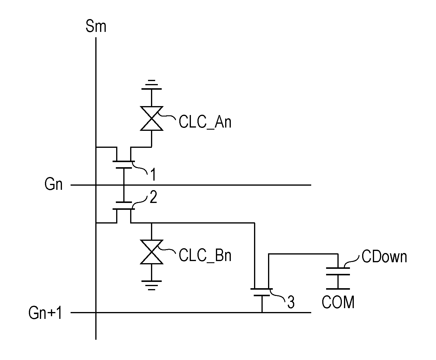
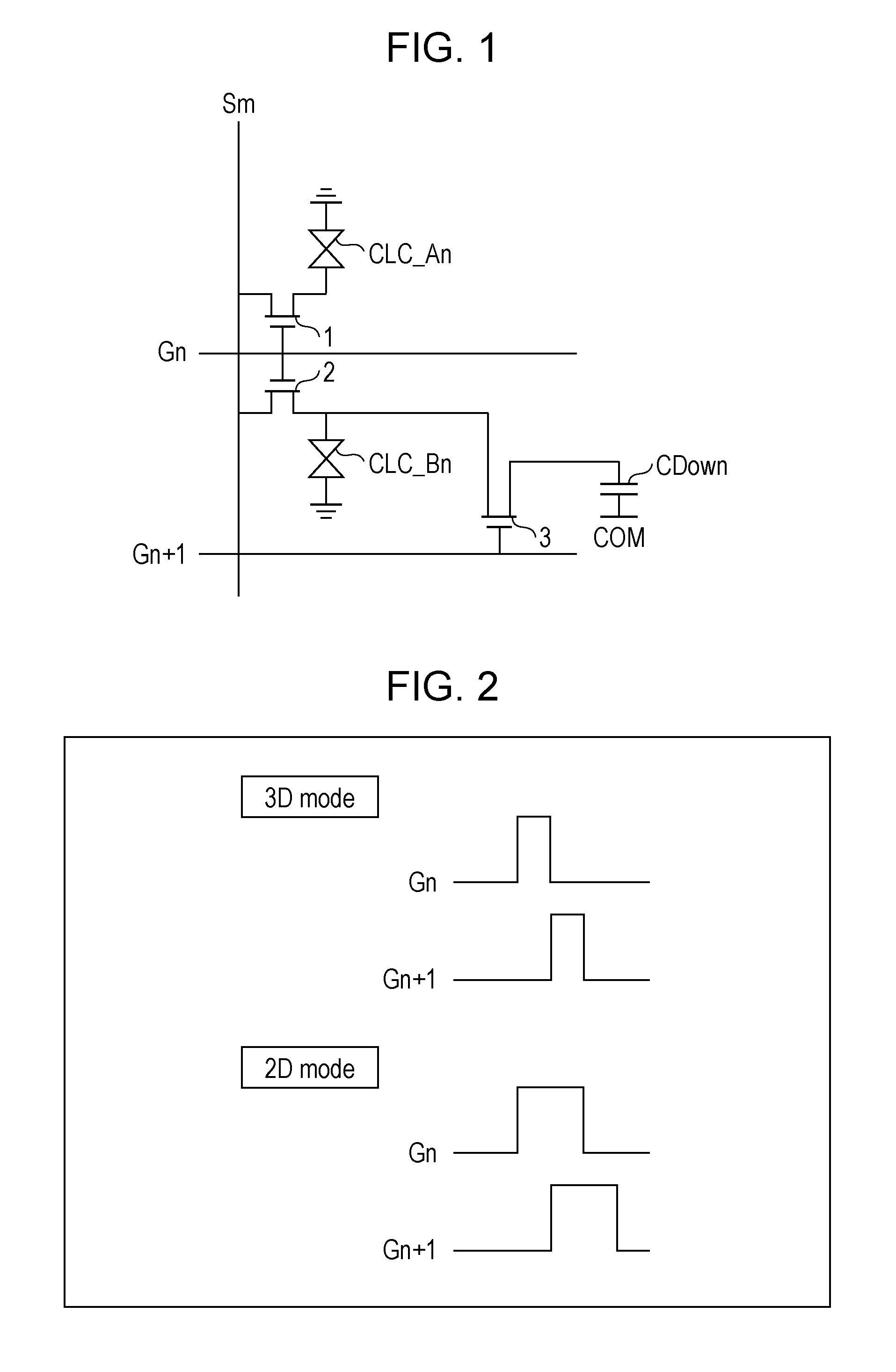
[0176]FIG. 32 is a circuit diagram illustrating a modification example of the basic pixel circuit illustrated in FIG. 1. Only the difference between the circuit diagram in FIG. 32 and that in FIG. 1 is that a control capacitor CDown (first control capacitor) is connected between the pixel electrode of, for example, the sub-pixel R2 among the two sub-pixels R1 and R2 and a common signal line COM through a TFT 3 (first switching element) whose gate electrode is connected to the gate signal line Gn+2. Note that a gate pulse for selecting the pixels in the (n+2)-th line is supplied to the gate signal line Gn+2.

[0177]In a driving method according to this modification example, the gate signal line Gn+2 in the (n+2)-th line is not restrictively used, and the gate signal line Gn+i in the (n+i)-th line (i is an integer greater than or equal to 2) may be used.

[0178]In accordance with the modification of the configuration of the pixel circuit from the configuration illustrated in FIG. 1 to the...

embodiment 2

[0192]Another embodiment of the present invention will be described hereinafter with reference to FIGS. 7 to 11. For convenience of illustration, the same components as those in the foregoing embodiment are assigned the same numerals, and a detailed description thereof is omitted.

[0193](Overview of Difference from Embodiment 1)

[0194]FIG. 11 is an explanatory diagram illustrating an example configuration of pixels in a liquid crystal display device according to this embodiment. A liquid crystal display device described in Embodiment 2 and the following embodiments has a configuration in which the configuration according to Embodiment 1 and a multi-pixel structure (MPD structure: Multi Pixel Drive structure), which is suitable for use in a VA mode or TN mode liquid crystal display device, are used in combination.

[0195]More specifically, for example, as indicated by sub-pixels R1 to R3 in FIG. 11, the number of sub-pixels per pixel is greater than or equal to three, and the number of n...


PUM


Abstract

A control capacitor (CDown) is connected between a pixel electrode of a liquid crystal capacitor (CLC_Bn) in at least one sub-pixel and a common signal line (COM) through a TFT (3) whose gate electrode is connected to a gate signal line (Gn+1), and a control circuit selectively switches output modes in accordance with whether the pulse periods of a gate pulse to be output to the gate signal line (Gn) and a gate pulse to be output to the gate signal line (Gn+1) partially overlap or not.

Description

TECHNICAL FIELD[0001]The present invention relates to a liquid crystal display device that displays an image using liquid crystals. More specifically, the present invention relates to a liquid crystal display device that stereoscopically displays an image by using a Patterned Retarder, and to a method for driving the liquid crystal display device.BACKGROUND ART[0002]In recent years, liquid crystal display devices having a function for stereoscopically displaying an image (hereinafter also referred to as “displaying a 3D (stereo) image”) in addition to a function for two-dimensionally displaying an image (hereinafter also referred to as “displaying a 2D (flat) image”) have been developed.[0003]Technologies for displaying a stereo image, such as an active shutter system, a lenticular system, and a patterned retarder system (or a polarization system, also called a PR system) are known. In any of the systems, presenting a right-eye image only to the right eye of a user and a left-eye im...

Claims


Application Information

Patent Timeline
IPC IPC(8): G09G3/36G02B30/25
CPCG02F1/13624G09G2310/08G02F2001/134345G02F2201/52G09G3/3648G09G2300/0426G09G2300/0443G09G2300/0447G09G2310/0205G09G2320/0209H04N13/0434H04N13/0454H04N13/0497G09G3/3611G02B27/2264G02B27/26G02F1/136213G09G3/003H04N13/0422G02F2001/133631H04N13/324H04N13/337H04N13/359H04N13/398G02B30/25G02B30/24G02F1/133631G02F1/134345
Inventor KAMADA, TSUYOSHI
Owner SHARP KK
Why Eureka
Try Eureka