Method and apparatus for a solid state light source

a solid-state light source and method technology, applied in the field of methods and apparatuses, can solve the problems of further reducing the quantum efficiency of the light source, and achieve the effects of low heat generation of individual phosphor particles, high efficiency, and high transmittan

Active Publication Date: 2013-09-05
APPOTRONICS CORP LTD
View PDF33 Cites 44 Cited by
  • Summary
  • Abstract
  • Description
  • Claims
  • Application Information

AI Technical Summary

Benefits of technology

[0024]In various embodiments of this invention, the phosphor's emission light is generated from a moving phosphor device, which may be a rotating phosphor disk, a rotating phosphor drum, a linearly moving phosphor plate, etc. The reason for using a moving device is to lower the heat generation for individual phosphor particles. The movement of phosphor plate with respect to the excitation light effectively converts the phosphor working mode from a continuous wave mode to a pulse mode.
[0025]In a light source according to one embodiment of the present invention, the phosphor device is coated with a high efficiency yellow phosphor layer. A blue light is used as the excitation source. The emission from such a phosphor is collected into a collimated beam. A dichroic filte

Problems solved by technology

The Stokes shift loss will turn into heat and raise the working temperatu

Method used


Image

  • Method and apparatus for a solid state light source
  • Method and apparatus for a solid state light source
  • Method and apparatus for a solid state light source

Examples


Embodiment Construction

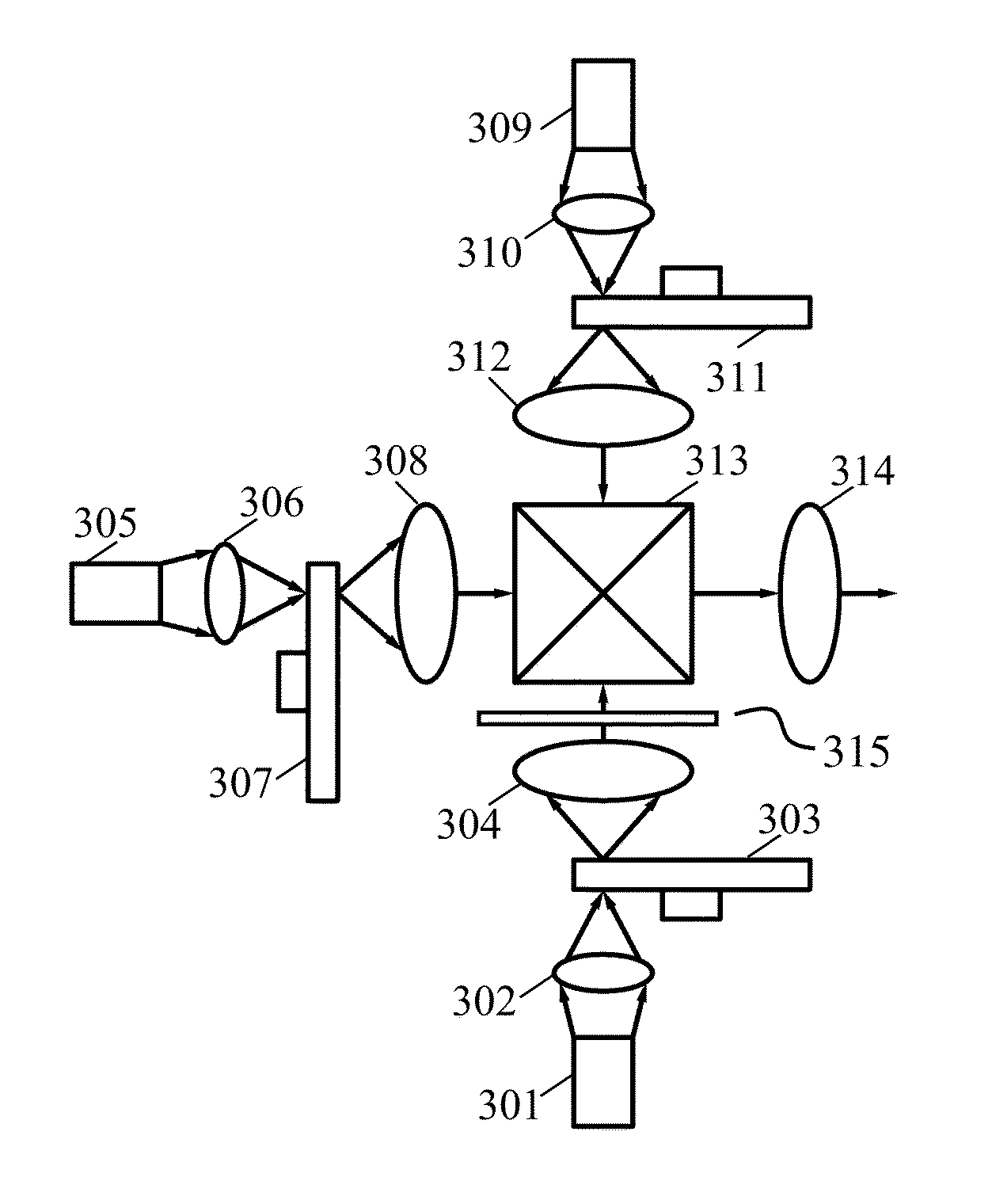
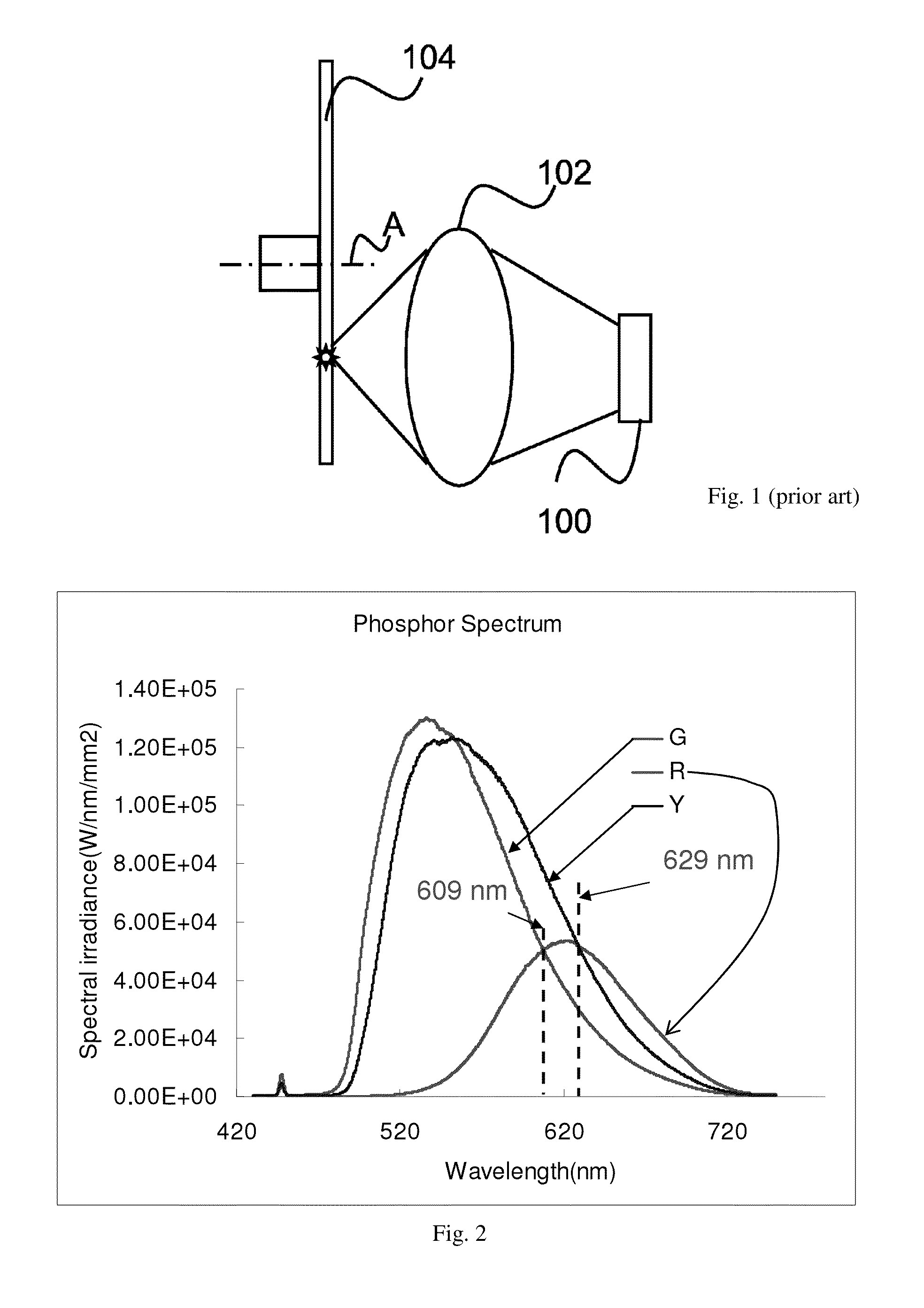
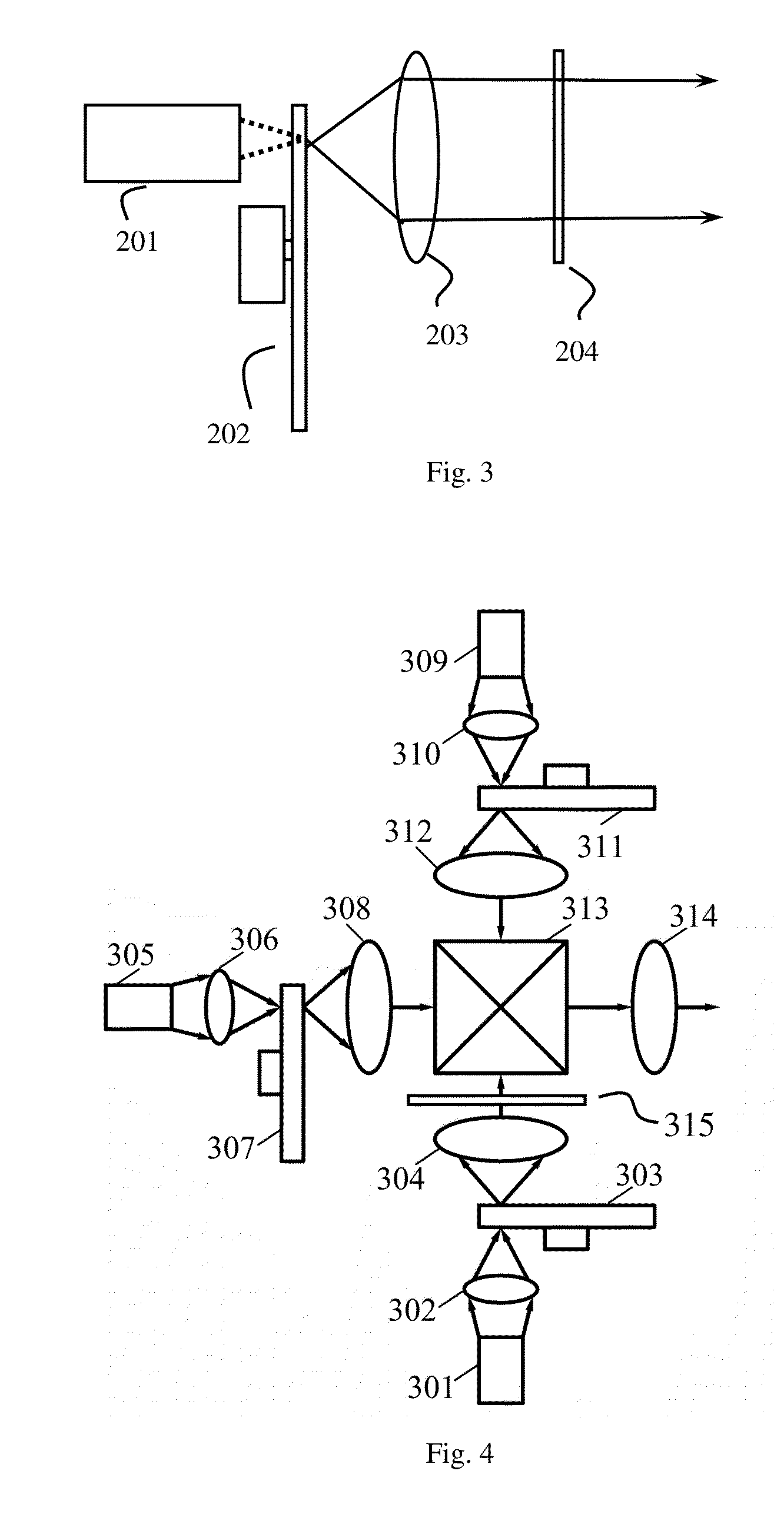
[0040]A light source device uses a wavelength down conversion material for absorbing an excitation light and generating a converted light, and a color filter for filtering the converted light to generate a different color light as output. The wavelength conversion material is a yellow or green phosphor which absorbs blue or UV light and generates a yellow or green converted light, which has a sufficiently wide spectrum to cover some of the red color region. The color filter only allows the red component of the converted light to be output. This system is more energy efficient than using a red phosphor. This light source may be implemented as a moving phosphor wheel having multiple segments, one of which being the yellow or green phosphor with the corresponding color filter, the other segments being used to generate other colored lights such as green and blue lights. Various embodiments are described in detail below.

[0041]FIG. 3 shows a light source device according to one embodiment...


PUM


Abstract

A light source device uses a wavelength down conversion material for absorbing an excitation light and generating a converted light, and a color filter for filtering the converted light to generate a different color light as output. The wavelength conversion material is a yellow or green phosphor which absorbs blue or UV light and generates a yellow or green converted light, which has a sufficiently wide spectrum to cover some of the red color region. The color filter only allows the red component of the converted light to be output. This system is more energy efficient than using a red phosphor. This light source may be implemented as a moving phosphor wheel having multiple segments, one of which being the yellow or green phosphor with the corresponding color filter, the other segments being used to generate other colored lights such as green and blue lights.

Description

[0001]This application claims priority under 35 USC §119(e) from U.S. Provisional Patent Application No. 61 / 528,218, filed Aug. 27, 2011, which is herein incorporated by reference in its entirety.BACKGROUND OF THE INVENTION[0002]1. Field of the Invention[0003]The present invention is in the technical field of light sources, and more particularly, light sources useful in applications that requires high luminance, such as projection displays and stage lighting.[0004]2. Description of the Related Art[0005]Many applications need colored light, such as stage lighting, projection display, RGB backlighting etc. Conventional high luminance light sources used in special lighting and displays are gas discharge lamps. An environmental-friendly technology is described in U.S. Pat. No. 7,547,114. In this light source structure, shown in FIG. 1, a solid-state light source 100 is used to emit an excitation light through a focusing system 102, and a rotation phosphor wheel 104, in which several col...

Claims


Application Information

Patent Timeline
IPC IPC(8): F21V9/16G03B21/20
CPCF21V7/22F21V9/16H04N9/3158F21W2131/406H04N9/3161G03B21/204F21V13/14F21V7/26F21V9/38F21V9/45
Inventor HU, FEILI, YI
Owner APPOTRONICS CORP LTD
Why Eureka
Try Eureka