
Crimping Sleeve for Crimped Connections

Active Publication Date: 2013-09-05
STOCKO CONTACT
View PDF5 Cites 4 Cited by
  • Summary
  • Abstract
  • Description
  • Claims
  • Application Information

AI Technical Summary

Benefits of technology

The patent is about a connecting element with a crimp barrel for securing wires. The base part of the connecting element is designed to have a constant thickness in the uncurved state, which provides stability to withstand pressure while making the crimped connection. The connecting element also has an insulation crimp that protects the crimped connection against mechanical and vibrational effects. The insulation crimp and the functional part of the connecting element are made of the same material to ensure a proper connection. The invention enables a reliable and durable crimped connection between wires and the crimp barrel.

Problems solved by technology

These tools are usually operated by a toggle mechanism since manual force is not sufficient to achieve a permanent deformation of the crimp barrel.
However, if insufficient force is applied during the crimping procedure or if the crimping tool used is too big, then the small-gauge conductors are inadequately compressed.
This brings about an increase in the transfer resistance between the conductor and the crimp barrel due to corrosion of the individual small-gauge conductors.
Moreover, the risk exists that an incompletely compressed conductor can be pulled out of the crimp barrel.
This can cause the current carrying capacity of the connection to be impermissibly diminished as a result of the reduced cross section.
Moreover, if the compressive force is exceeded to an extreme extent, there is a risk that, in the case of small-gauge conductors, individual conductors might be sheared off.
Furthermore, the crimp barrel can become unusable if it cracks or ruptures.

Method used


Image

  • Crimping Sleeve for Crimped Connections
  • Crimping Sleeve for Crimped Connections
  • Crimping Sleeve for Crimped Connections

Examples


Embodiment Construction

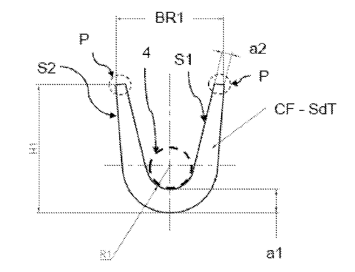
[0027]FIG. 1 shows a crimp barrel (CF-SdT) in a pre-bent shape in a side view (sectional view perpendicular to the later wire direction in the crimped connection) according to the state of the art. The pre-bent shape (crimp shape CF) is in the form of a “V” with a curved base and crimping wings facing upward that are at a maximum distance BR1 from each other, namely, the width of the crimp shape CF. The radius of curvature R1 of the curved base is dimensioned in such a way that a wire 4 having a certain cross section can be laid into the curved base. In order to achieve a radius of curvature R1 that is suitable for the wire 4, the base has to have a thickness a1. The crimp barrel has a first side S1 that faces the wire when the crimped connection has been made, and a second side S2 that is the side of the crimp barrel that is opposite from S1. The tips of the crimping wings P have a thickness a2 that is smaller than the thickness a1, so that the crimping wings can roll up during the...


PUM


Abstract

The invention relates to a crimping sleeve comprising a base part and at least two deformable crimping blades for producing a crimped connection to a cable, wherein the crimping blades each comprise a first region connected to the base part, a second region, and a middle region disposed between the first and the second regions, and wherein the base part comprises a greater thickness than the middle region of the crimping blades, the first region tapers down from the base part toward the middle region at least on a first side and the second region further tapers down from the middle region, starting at least on a second side opposite the first side, said sleeve thereby being equally suitable for cables having different cross sections for producing a reliable connection between the cables and crimping sleeve. The invention further relates to a connecting element having such a crimping sleeve.

Description

FIELD OF THE INVENTION[0001]The invention relates to a crimp barrel and to a connecting element having such a crimp barrel.BACKGROUND OF THE INVENTION[0002]Joining methods with which two components are mechanically connected to each other by means of plastic deformation are used, among other places, in electrical engineering. Such mechanical joining methods are also referred to as crimping and constitute an alternative to conventional connections such as soldering or welding. Crimping is used especially to create a homogeneous connection between a conductor and a connecting element that is difficult to undo and that ensures high electrical and mechanical reliability. The connecting element is often a plug with an appropriate crimp barrel. Wherever it is not easily possible to lay a wire that already has plugs, the wire alone is laid all the way to its destination site and only there is an electric contact part installed at the end of the conductor (for example, by crimping a plug on...

Claims


Application Information

Patent Timeline
IPC IPC(8): H01R4/20
CPCH01R4/184H01R4/20H01R43/16H01R13/05
Inventor LENGERT, CLAUDEACKERMANN, DANIEL
Owner STOCKO CONTACT
Features
  • Generate Ideas
  • Intellectual Property
  • Life Sciences
  • Materials
  • Tech Scout
  • Unparalleled Data Quality
  • Higher Quality Content
  • 60% Fewer Hallucinations
Learn More