Light fixture monitoring-control system and method

a technology for monitoring and controlling systems, which is applied in computer control, data switching networks, instruments, etc., can solve the problems of inability to work in a coordinated fashion with dimmer systems, inability to control dimmer systems from the ubiquitous internet, and inability to work with other home devices (sensors in particular)

Active Publication Date: 2013-09-05
ADVANERGY
View PDF1 Cites 15 Cited by
  • Summary
  • Abstract
  • Description
  • Claims
  • Application Information

AI Technical Summary

Benefits of technology

[0037]The present invention describes a product that allows consumers to control (turn on and off and dim) light bulbs (and associated lamp fixtures) anywhere at home or away via an Internet-capable device (e.g., a smartphone, a tablet, or a lapto

Problems solved by technology

The prior art as detailed above suffers from the following deficiencies:Prior art dimmer systems cannot be controlled from ubiquitous Internet.Prior art dimmer systems cannot work with other home devices (sensors in particular) as a coordinated system.Prior art dimmer systems cannot work in a coordinated fashion to form security networks.Prior art dimmer systems cannot support customized sensor modules.Prior art di

Method used


Image

  • Light fixture monitoring-control system and method
  • Light fixture monitoring-control system and method
  • Light fixture monitoring-control system and method

Examples


embodiment

Preferred Embodiment Method Summary

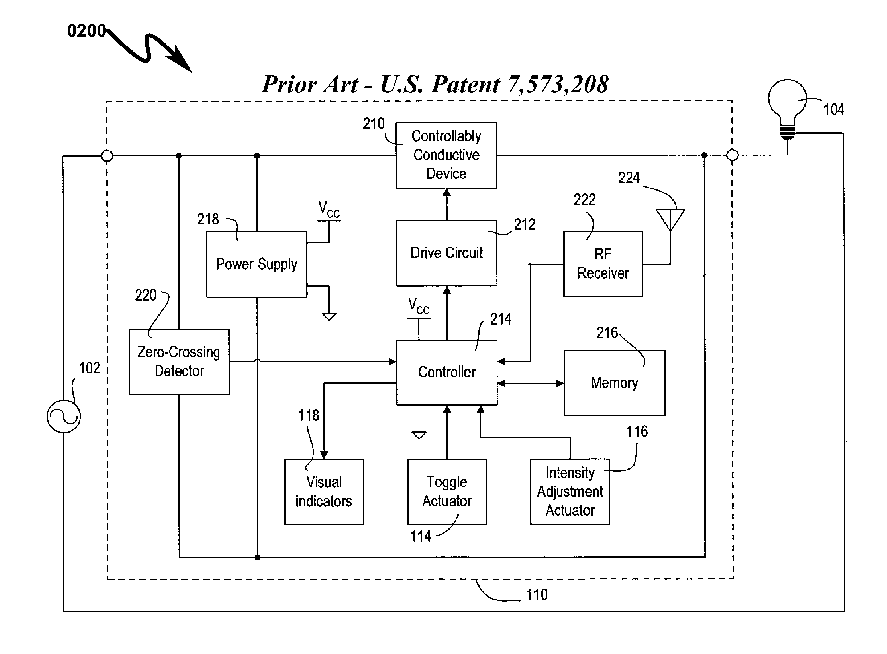
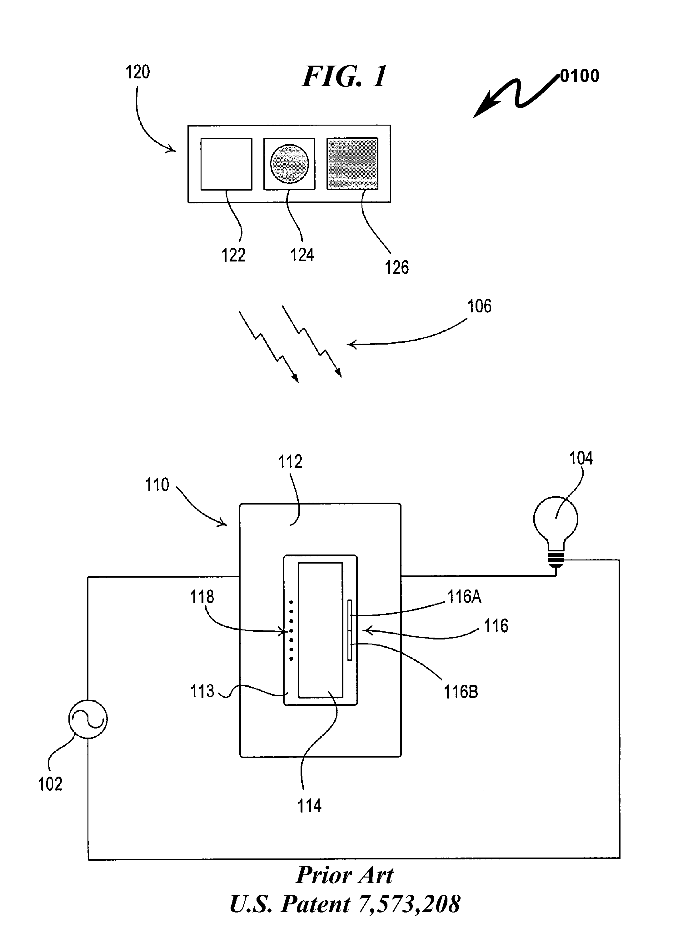
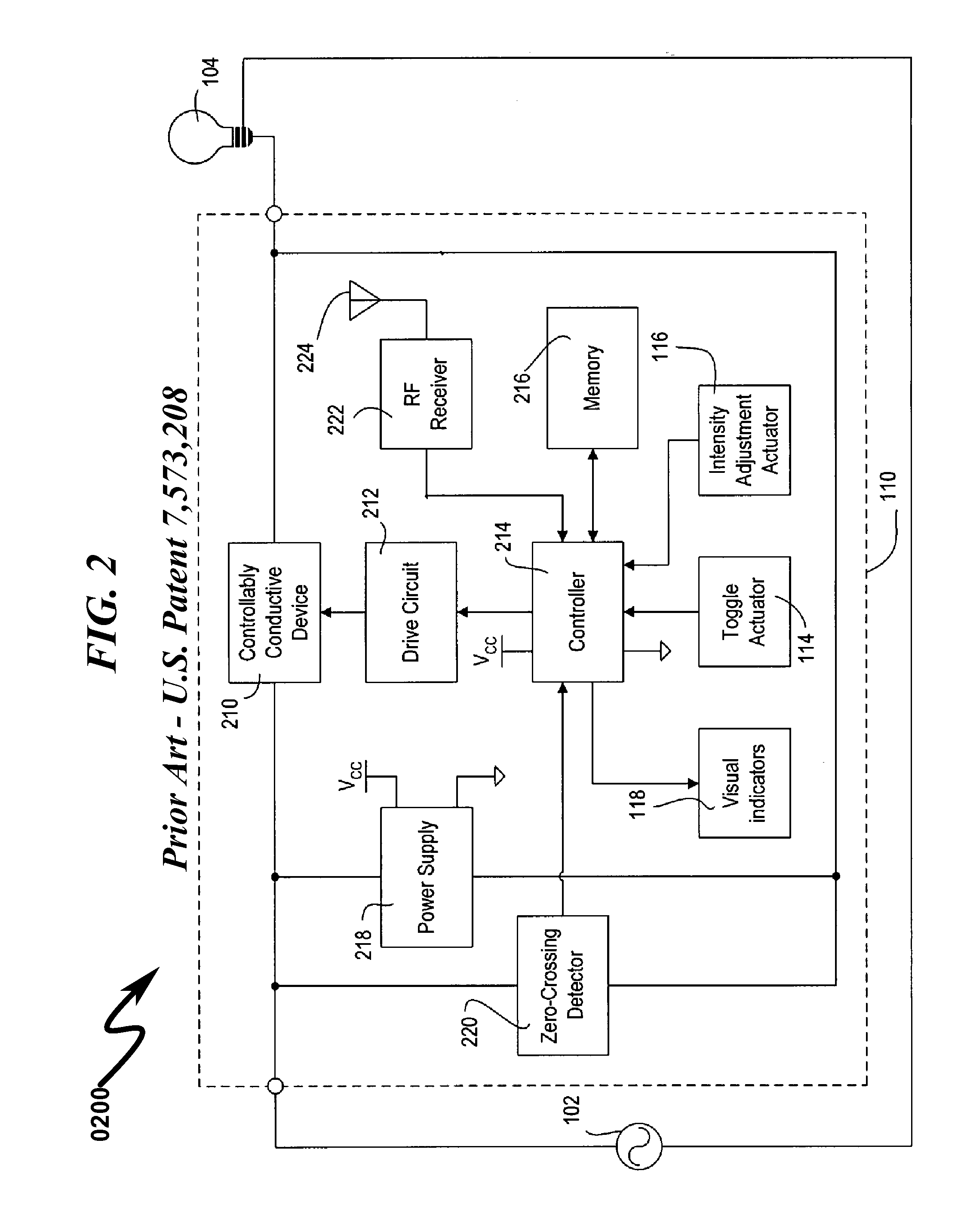
[0194]The present invention preferred exemplary method embodiment anticipates a wide variety of variations in the basic theme of implementation, but can be generalized as a light fixture monitoring / control method, the method operating in conjunction with a light fixture monitoring / control system comprising:[0195](a) source electrical input connector (SEIC); and[0196](b) sink electrical output connector (SEOC);[0197](c) lamp dimmer control (LDC);[0198](d) integrated computing device (ICD);[0199](e) light fixture adapter sensor (LFAS); and[0200](f) wireless communication interface (WCI);[0201]wherein[0202]the LDC is configured to control the flow of electrical current from the SEIC to the SEOC under direction of the ICD;[0203]the ICD is configured to monitor the LFAS;[0204]the ICD is configured to control the LDC in response to inputs from the LFAS;[0205]the ICD is configured to monitor the WCI;[0206]the ICD is configured to control the LDC in respon...


PUM


Abstract

A light fixture monitoring/control system/method allowing a lamp associated with a lighting fixture to be controlled in response to localized lighting fixture sensor inputs and/or remote wireless commands is disclosed. The system utilizes a light fixture adapter (LFA) as a dimming control and monitoring interface between a light fixture and the lamp installed in the LFA. Dimming control is directed by a computing device based on a LFA program (LFAP) that analyzes information from one or more sensors integrated within the LFA. The LFA supports a web-based browser interface and a wireless communication link allowing remote users to define the LFAP and/or directly control lamp dimming and/or access data from LFA sensors. The LFA permits low-cost retrofitting of existing light fixtures with “smart” networked lighting controls that may incorporate advanced spatially diverse security monitoring functions including audio and/or video surveillance.

Description

CROSS REFERENCE TO RELATED APPLICATIONSU.S. Utility Patent Applications[0001]This application claims benefit under 35 U.S.C. §120 and incorporates by reference United States Utility Patent Application for BATTERY CHARGER MANAGEMENT SYSTEM AND METHOD by inventors Jin (nmn) Lu and Todd Scott Kelly, filed electronically with the USPTO on Mar. 15, 2013, with Ser. No. 13 / 840,022, EFS ID 15264235, confirmation number 9841, docket AADVN.0106.[0002]This application claims benefit under 35 U.S.C. §120 and incorporates by reference United States Utility patent application for DATA SERVER SYSTEM AND METHOD by inventors Jin (nmn) Lu and Todd Scott Kelly, filed electronically with the USPTO on Oct. 4, 2012, with Ser. No. 13 / 645,080, EFS ID 13911815, confirmation number 3882, docket AADVN.0104.[0003]This application claims benefit under 35 U.S.C. §120 and incorporates by reference United States Utility patent application for NETWORK INTEGRATION SYSTEM AND METHOD by inventors Jin (nmn) Lu and Todd...

Claims


Application Information

Patent Timeline
IPC IPC(8): G05B15/02
CPCH04L12/2807H04L12/2836H04L12/2818G05B15/02H04L12/66
Inventor LU, JINKELLY, TODD SCOTTCHEUNG, LEE
Owner ADVANERGY
Why Eureka
Try Eureka