Composite wire of silver-palladium alloy coated with metallic thin film and method thereof

a technology of silver-palladium alloy and composite wire, which is applied in the direction of coatings, semiconductor devices, conductors, etc., can solve the problems of reducing the bonding strength the pad, the hardness of the bonding wire may not be too high, and the resin used in the package generally has corrosive chloride ions and environmental moisture absorption, etc., to achieve excellent properties of thermal conductivity, tensile strength, ionic migration resistan

Inactive Publication Date: 2013-09-12
WIRE TECH +1
View PDF0 Cites 15 Cited by
  • Summary
  • Abstract
  • Description
  • Claims
  • Application Information

AI Technical Summary

Benefits of technology

[0017]The present invention is to provide a composite wire comprising an alloy core member and a plating layer forming on a surface of the alloy core member, wherein the alloy core member may be of Ag—Pd alloy and the plating layer having at least one layer of pure gold, pure palladium or Au—Pd alloy thin film. The composite wire has excellent properties of thermal conductivity, electr

Problems solved by technology

However, the hardness of bonding wires may not too high; otherwise the chip may crack during hot pressing of wire bonding and bonding strength of bonding wires and pads may be reduced.
Also, resins used in the packages generally have corrosive chloride ions and environmental moisture absorption.
When the semiconductor package products and LED package products are in use, a high current density that flows through the bonding wire may cause electromigration of metallic atoms of the bonding wire.
The aluminum-silicon alloy wire has a low strength and is easy to be corrosive so that it only can be used in electronic products which have a low requirement of reliability.
The pure gold wire is a main stream in the bonding wires, but it is expensive to cause a high cost of the package product and a large number of brittle intermetallic compounds that may reduce reliability of contacts may be formed on an interface of pure gold wire and aluminum pad.
However, the copper is easy to be corrosive so that a surface protection is required for wire storage and transportation, and inert gas including nitrogen and hydrogen is required for wire binding.
Moreover, because the material of pure copper wire is too hard, a great force may cause damage to a chip in the process of wire bonding.
The material of pure copper wire and pure copper wire covered a plating layer is too hard to apply in an advanced wire bonding technology of double ball stack.
However, wire bonding of mixing gold wire and copper wire causes a high material cost, poor bonding strength and high risk of galvanic corrosion at an interface between Au and Cu.
Although a pure copper wire plating a metallic layer may avoid surface oxidation and corrosion of copper wire, those plating layers of Au, Pd or Pt may be melted into copper bonding ball during formation of a ball of wire bonding so that the completed ball bond only has few element of the plating layer on its surface, and thus may be not effective to prevent package products from corrosion.
Also, even though a pure copper wire has been plated a metallic layer, the material of pure copper wire acting as core member is too hard, a great force may cause damage to a chip in the process of wire bonding.
The material of pure copper wire and pure copper wire co

Method used


Image

  • Composite wire of silver-palladium alloy coated with metallic thin film and method thereof
  • Composite wire of silver-palladium alloy coated with metallic thin film and method thereof
  • Composite wire of silver-palladium alloy coated with metallic thin film and method thereof

Examples


examples

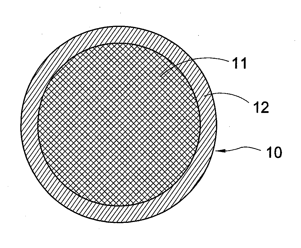
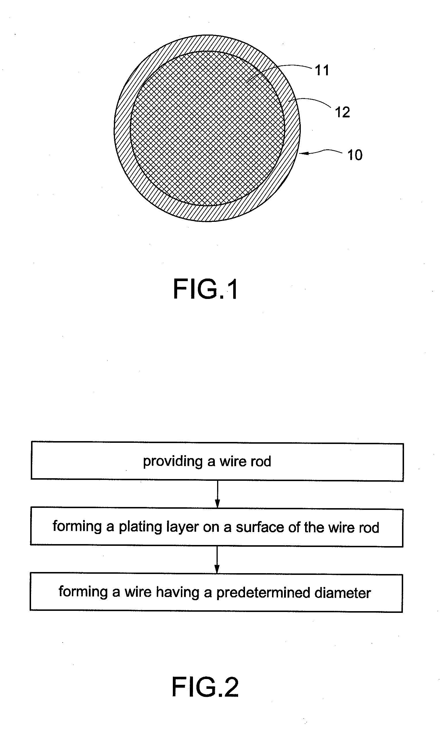
[0045]An Ag-3.5 wt % Pd alloy wire is used as alloy core member 11 of the invention. The test results of properties of an Ag-3.5 wt % Pd alloy wire with a plating layer of pure gold thin film, an Ag-3.5 wt % Pd alloy wire with a plating layer of pure palladium thin film and an Ag-3.5 wt % Pd alloy wire with a plating layer of Au—Pd alloy thin film compared to the Ag-3.5 wt % Pd alloy wire without a plating layer are shown in table 1. Also, the results of reliability test of the Ag-3.5 wt % Pd alloy wire with a plating layer of pure gold thin film, the Ag-3.5 wt % Pd alloy wire with a plating layer of pure palladium thin film and the Ag-3.5 wt % Pd alloy wire with a plating layer of Au-Pd alloy thin film are shown in table 2.

TABLE 1Test results of properties of composite wires platingwith a metallic thin film compared to an Ag-3.5wt % Pd alloy wire without a plating layerComposite wiresAu—Pd alloyPropertiesAu thin filmPd thin filmthin filmFormation ofHigherHigherHigherwire drawingEle...


PUM


Abstract

The invention provides a composite wire for electronic package, the composite wire including an alloy core member and a plating layer forming on a surface of the alloy core member. The alloy core member is silver-palladium alloy. The plating layer is at least one layer of thin film of pure gold, pure palladium or gold-palladium alloy. The invention also provides a method for manufacturing the composite wire. The method includes steps of: (a) providing a wire rod, (b) forming a wire having a predetermined diameter from the wire rod by a plurality of processes including cold working and annealing and (c) forming a plating layer on a surface of the wire rod before step (b) or forming a plating layer on a surface of the wire after step (b) by electroplating, sputtering or vacuum evaporation.

Description

BACKGROUND OF THE INVENTION[0001]1. Field of the Invention[0002]The present invention generally relates to a composite wire and method thereof, in particular to an alloy wire for wire bonding of electronic package and method thereof.[0003]2. Description of Related Art[0004]Wire bonding is one of important steps of semiconductor package and light emitting diodes package. Besides providing signal and power transmission of chips and substrates, bonding wires also has a function of heat dissipation. Therefore, the bonding wires should have excellent electrical conductivity and thermal conductivity, and sufficient strength and ductility. However, the hardness of bonding wires may not too high; otherwise the chip may crack during hot pressing of wire bonding and bonding strength of bonding wires and pads may be reduced. Also, resins used in the packages generally have corrosive chloride ions and environmental moisture absorption. Accordingly, the bonding wires must have good oxidation-res...

Claims


Application Information

Patent Timeline
IPC IPC(8): H01B1/02H01B13/30
CPCH01B1/02H01L2224/43H01L24/45H01L2224/45565H01L2224/45144H01L2224/45147H01L24/43H01L2224/45015H01L2224/45139H01L2224/45664H01B13/30H01L2924/01047H01L2924/01006H01L2924/00014H01L2924/01046H01L2924/00015H01L2224/45644H01L2924/20751H01L2924/20752H01L2924/20753H01L2924/20754H01L2924/20755H01L2924/013H01L2924/00H01L2224/48H01L2924/00011H01L2224/05624H01L2224/4321H01L2224/43848H01L2224/45639H01L2224/45655H01L2224/45669H01L2224/45673H01L2224/48511H01L2224/48624H01L2224/48824H01L2224/85206H01L2924/20104H01L2924/20105H01L2924/01049
Inventor LEE, JUN-DERTSAI, HSING-HUACHUANG, TUNG-HAN
Owner WIRE TECH
Why Eureka
Try Eureka