Liquid ejecting head and liquid ejecting apparatus

a liquid ejecting and liquid ejecting technology, which is applied in the direction of printing, movable spraying apparatus, inking apparatus, etc., can solve the problems of defect, rapid flow of ink inside the pressure generation chamber, and defect in the landing of variation, so as to achieve favorable ejection characteristics and high-quality printed matter.

Active Publication Date: 2013-09-12
SEIKO EPSON CORP
View PDF3 Cites 43 Cited by
  • Summary
  • Abstract
  • Description
  • Claims
  • Application Information

AI Technical Summary

Benefits of technology

[0017]In the aspect, even if the recording head employing a circulation type is mounted, favorable ejection characteristics can be obtained. As a result, deterioration of the ejection characteristics due to the thickening of the li

Problems solved by technology

Thus, the ink is thickened by evaporation of moisture through the nozzle opening and it may cause adverse effect to ejection characteristics of the ink droplets.
In other words, when even a portion of the ink is thickened, an ejection amount and an ejection speed of the ink droplets via the nozzle opening are changed, and a defect, in which variation of the landing occurs, is generated.
However, in the recording head applying the circulation type described above, when the circulation amount of the ink is large, the flow of the ink inside the p

Method used


Image

  • Liquid ejecting head and liquid ejecting apparatus
  • Liquid ejecting head and liquid ejecting apparatus
  • Liquid ejecting head and liquid ejecting apparatus

Examples


first embodiment

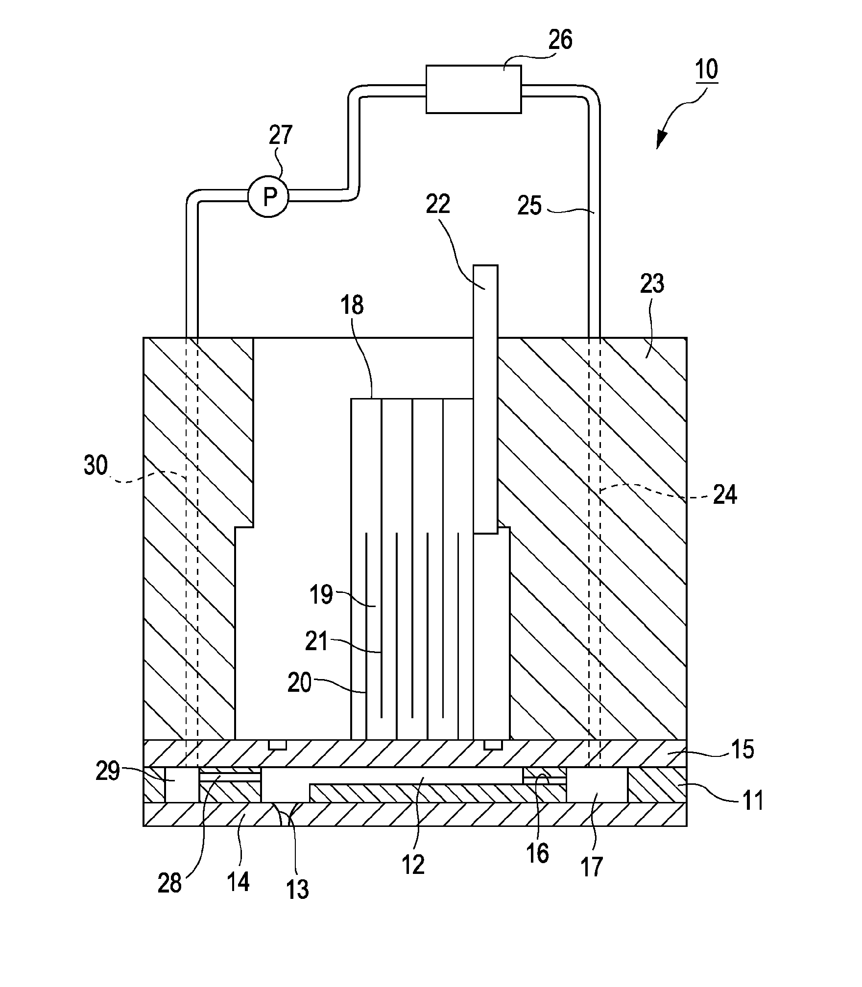
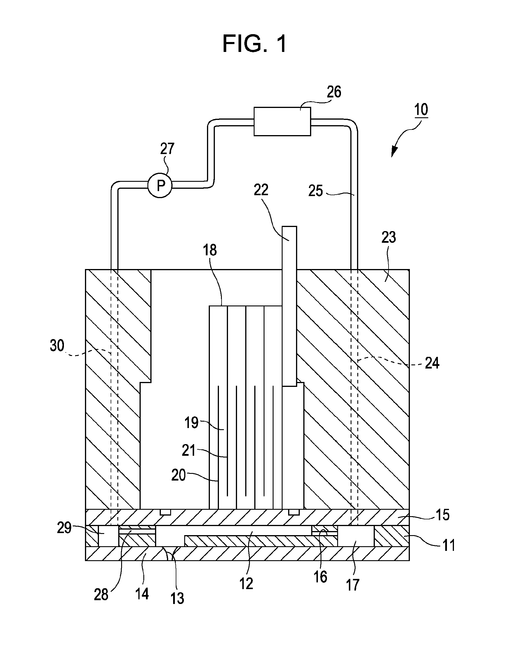
[0025]FIG. 1 is a cross-sectional view illustrating a recording head of the first embodiment of the invention. As illustrated in the same view, an ink jet type recording head 10 according to the embodiment is a type having a vertical vibration type piezoelectric element and is configuration such that a plurality of pressure generation chambers 12 are arranged parallel to each other in a flow path substrate 11 and both sides of the flow path substrate 11 in the thickness direction (in the vertical direction in the drawing) are sealed by a nozzle plate 14 having a nozzle opening 13 with respect to each of pressure generation chambers 12 and a vibration plate 15. Here, the nozzle opening 13 is formed in a taper shape of which the diameter is gradually reduced toward the opening.

[0026]In addition, the flow path substrate 11 has a first manifold 17 which is a first liquid storage section that is a common ink chamber of the plurality of pressure generation chambers 12 by communicating wit...

second embodiment

[0037]FIG. 3 is a cross-sectional view which is taken along a line III-III of the recording head in FIG. 4 according to the second embodiment of the invention. FIG. 4 is a schematic plan view illustrating planarly the flow path substrate in FIG. 3.

[0038]As illustrated in FIGS. 3 and 4, a recording head 100 according to the embodiment is configured by joining two recording heads 10, as illustrated in FIGS. 1 and 2, to face each other. At this time, the nozzle row, in which one side and the other side nozzle openings 131 and 132, arranged in a nozzle plate 140, is configured such that the nozzle openings 131 and 132 adjacent to each other in the nozzle row direction are arranged in a zigzag shape. In addition, the front portions of pressure generation chambers 121 and 122 facing each other in a flow path substrate 110 communicate with each other through a circulation communication path 280. Here, since the nozzle openings 131 and 132 are arranged in the zigzag shape, the circulation c...


PUM


Abstract

A ink jet type recording head which circulates ink between a first manifold and a second manifold via a pressure generation chamber is provided, the flow path member has a first and second bypass flow paths which connect the first and second manifolds, respectively in two locations of one end side and the other end side of a nozzle row on the outside of the nozzle row on which the nozzle openings are formed, and a relationship between a flow path resistance R of the first and second bypass flow paths, and a flow path resistance r of a flow path portion including the pressure generation chamber which connects the first and second manifolds is R<r/N (wherein, N is the number of all nozzle openings).

Description

BACKGROUND[0001]1. Technical Field[0002]The present invention relates to a liquid ejecting head and a liquid ejecting apparatus, and more particularly, to a liquid ejecting head and a liquid ejecting apparatus which is useful when applied to those employing a circulation type in which a liquid is circulated via each of pressure generation chambers between a first and second manifolds which are liquid storage sections arranged in both sides across a plurality of pressure generation chambers having nozzle openings and communicating with each of the pressure generation chambers.[0003]2. Related Art[0004]As a liquid ejecting apparatus, for example, there is provided an ink jet type recording apparatus including an ink jet type recording head (hereinafter, simply referred to as a recording head) which has a plurality of pressure generation chambers which generates a pressure with a pressure generation unit configured of a piezoelectric element to eject ink droplets, an ink supply path wh...

Claims


Application Information

Patent Timeline
IPC IPC(8): B05B17/06
CPCB41J2/14274B05B17/0615B41J2202/12
Inventor UEZAWA, HARUHISA
Owner SEIKO EPSON CORP
Why Eureka
Try Eureka