Method of determining the rotor position of a permanent-magnet motor

a permanent magnet, rotor position technology, applied in the direction of multiple motor speed/torque control, synchronous motor starter, electronic commutator, etc., can solve the problems of complex integration of sensor within the motor, easy generation of electromagnetic noise, and low component cost of the sensor, so as to simplify the control of the motor and simple and cheap control system

Active Publication Date: 2013-09-12
DYSON TECH LTD
View PDF5 Cites 17 Cited by
  • Summary
  • Abstract
  • Description
  • Claims
  • Application Information

AI Technical Summary

Benefits of technology

[0023]The motor may comprise a single phase winding. This then has the advantage of simplifying the control of the motor. As a result, a relatively simple and cheap control system may be employed to implement the method. As noted above, the method is able to simultaneously drive and determine the position of the rotor. Accordingly, sensorless control of a single-phase motor may be achieved without compromising on electrical power.

Problems solved by technology

Although the component cost of the sensor is relatively cheap, integrating the sensor within the motor often complicates the design and manufacture of the motor.
Additionally, the signal output by the sensor is often susceptible to electromagnetic noise generated within the motor.
For a single-phase motor, the lack of additional phase windings makes this type of control unfeasible.
Unfortunately, suspending excitation has the disadvantage of reducing the electrical power that can be driven into the motor.

Method used


Image

  • Method of determining the rotor position of a permanent-magnet motor
  • Method of determining the rotor position of a permanent-magnet motor
  • Method of determining the rotor position of a permanent-magnet motor

Examples


Embodiment Construction

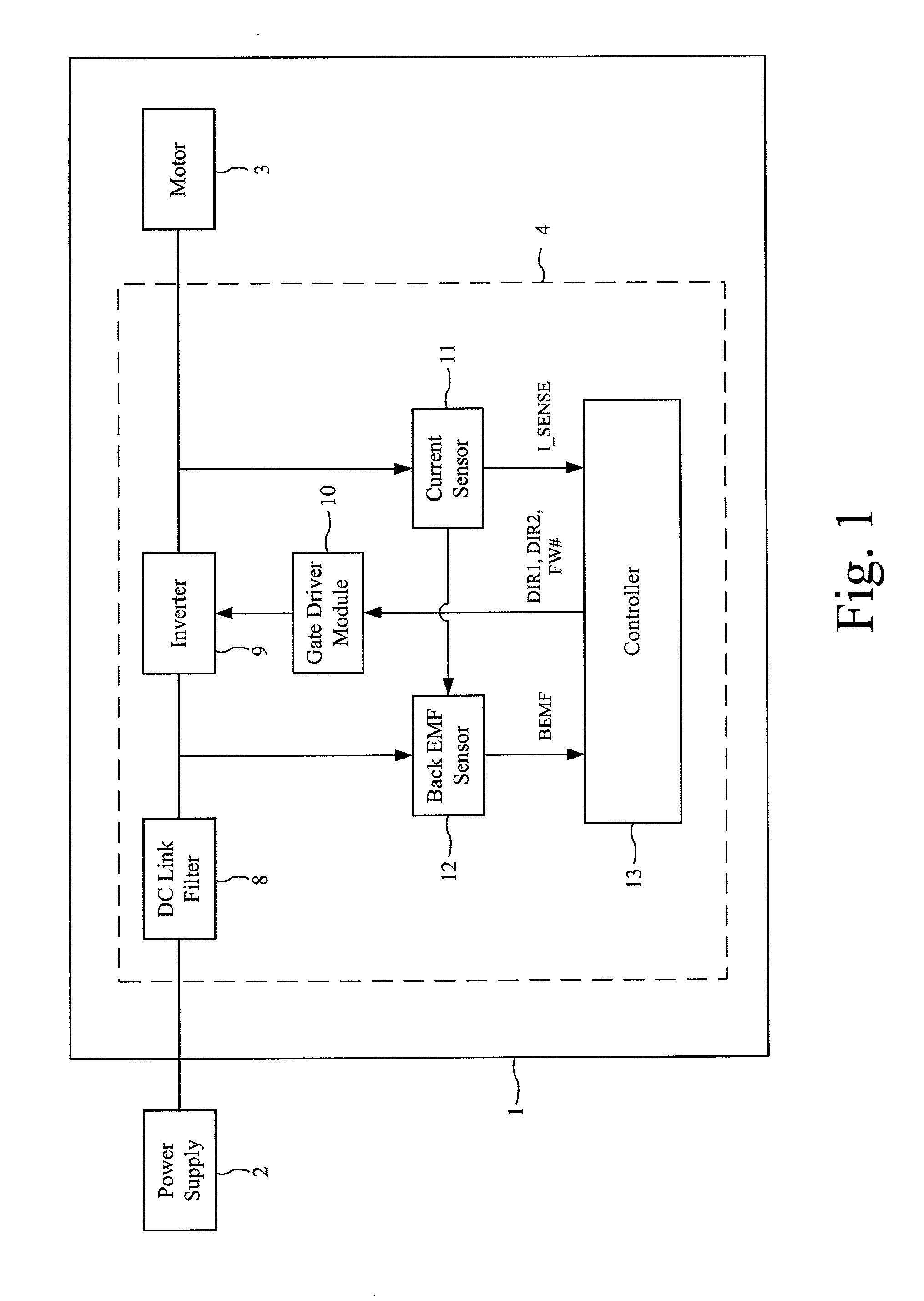
[0038]The motor system 1 of FIGS. 1 and 2 is powered by a DC power supply 2 and comprises a brushless motor 3 and a control system 4.

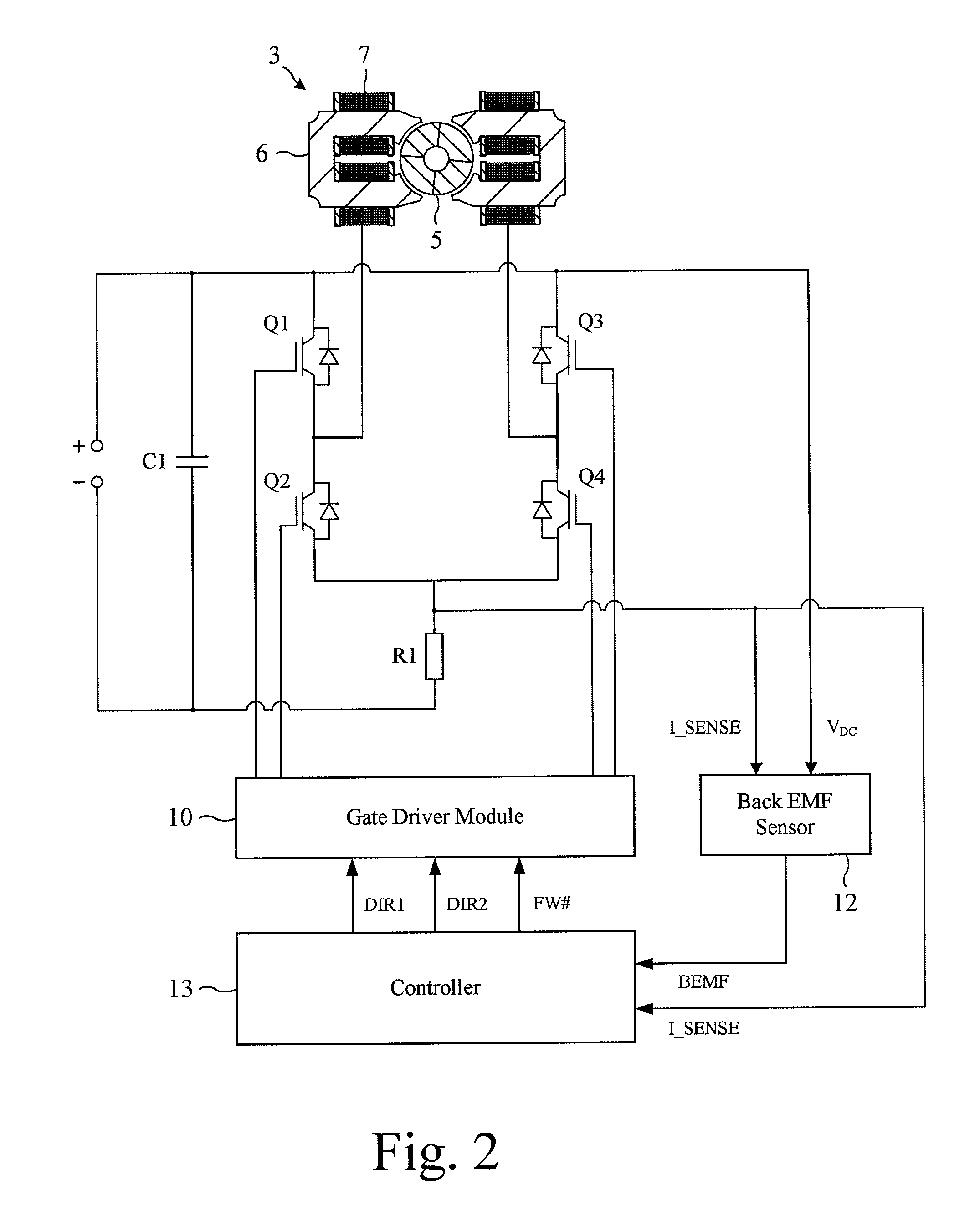
[0039]The motor 3 comprises a four-pole permanent-magnet rotor 5 that rotates relative to a four-pole stator 6. Conductive wires are wound about the stator 6 and are coupled together (e.g. in series or parallel) to form a single phase winding 7.

[0040]The control system 4 comprises a DC link filter 8, an inverter 9, a gate driver module 10, a current sensor 11, a back EMF sensor 12, and a controller 13.

[0041]The DC link filter 8 comprises a capacitor C1 that smoothes the relatively high-frequency ripple that arises from switching of the inverter 9.

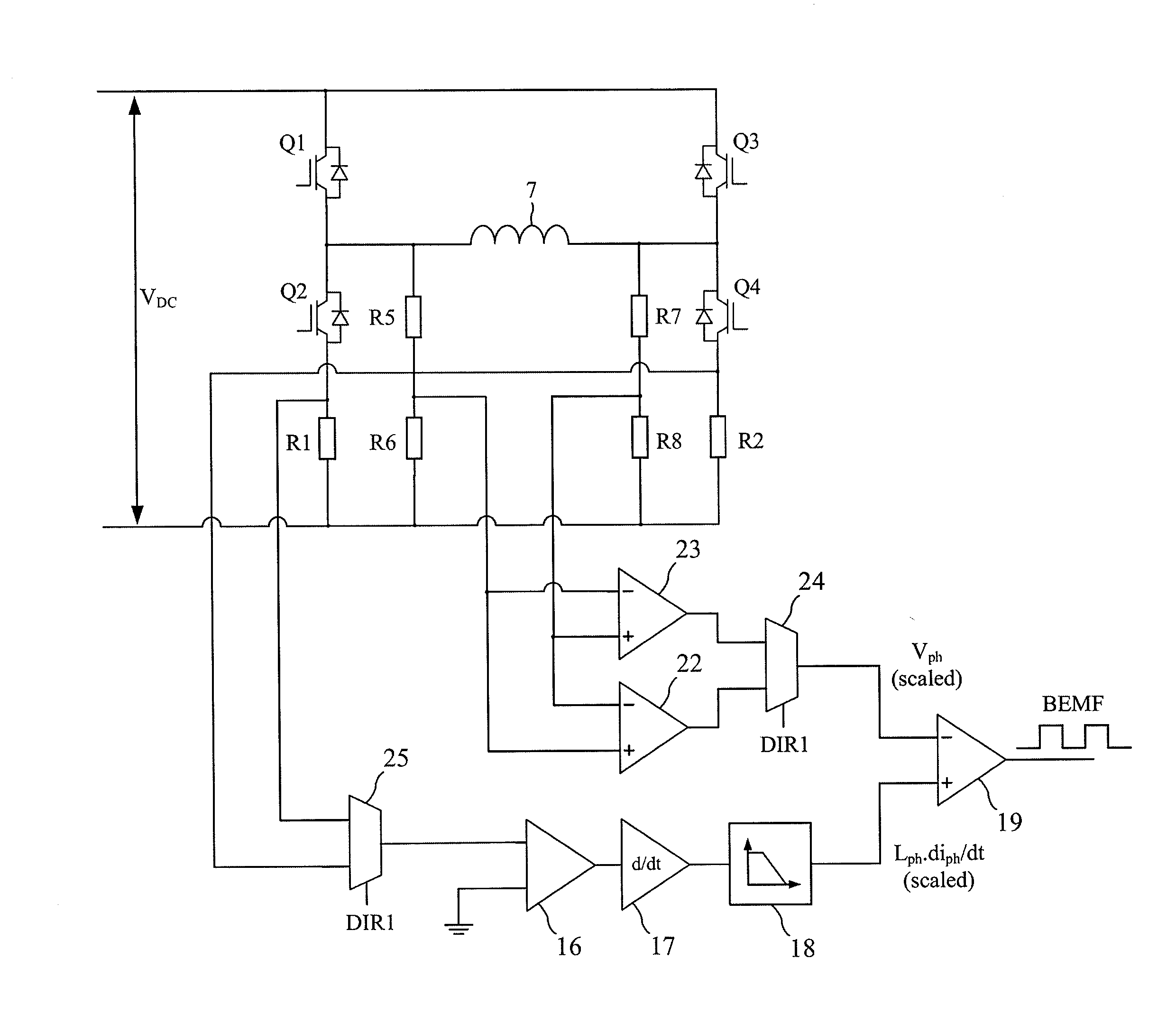
[0042]The inverter 9 comprises a full bridge of four power switches Q1-Q4 that couple the DC link voltage to the phase winding 7. Each of the switches Q1-Q4 includes a freewheel diode.

[0043]The gate driver module 10 drives the opening and closing of the switches Q1-Q4 in response to control signals received fr...


PUM


Abstract

A method of determining the position of a rotor of a permanent-magnet motor. The method uses two different schemes to determine the position of the rotor. A first scheme is used when the rotor rotates within a first speed range, by sequentially exciting and freewheeling a winding of the motor, measuring a parameter that depends on the rate of change of current in the winding, and comparing the parameter against a threshold. A second scheme is used when the rotor rotates within a second speed range, by generating a voltage signal that is proportional to the voltage across the winding, generating a further voltage signal that depends on the rate of change of current in the winding, and comparing the two signals.

Description

REFERENCE TO RELATED APPLICATIONS[0001]This application claims the priorities of United Kingdom Application No. 1203911.1, filed Mar. 6, 2012, United Kingdom Application No. 1203913.7, filed Mar. 6, 2012, and United Kingdom Application No. 1210371.9, filed Jun. 12, 2012, the entire contents of which are incorporated herein by reference.FIELD OF THE INVENTION[0002]The present invention relates to a method of determining the rotor position of a permanent-magnet motor.BACKGROUND OF THE INVENTION[0003]Knowledge of the rotor position is essential in order to commutate the phase windings of a brushless motor at the correct times. A permanent-magnet motor will often include a Hall-effect sensor, which outputs a signal indicative of the rotor position. Although the component cost of the sensor is relatively cheap, integrating the sensor within the motor often complicates the design and manufacture of the motor. Additionally, the signal output by the sensor is often susceptible to electromag...

Claims


Application Information

Patent Timeline
Patent Type & Authority Applications(United States)
IPC IPC(8): H02P23/00
CPCH02P6/008H02P23/00H02P6/185H02P6/182H02P6/181H02P6/188H02P2203/05H02P6/26Y10S388/9281
Inventor BATEMAN, CHRISTOPHER JOHN
Owner DYSON TECH LTD
Why Eureka
Try Eureka