Control of a brushless motor

a brushless motor and control technology, applied in current controllers, electronic commutators, synchronous motor starters, etc., can solve the problems of requiring a faster and more expensive controller, and achieve the effect of simple and cheap controller, simplified control, and simplified motor control

Inactive Publication Date: 2011-10-20
DYSON TECH LTD
View PDF7 Cites 18 Cited by
  • Summary
  • Abstract
  • Description
  • Claims
  • Application Information

AI Technical Summary

Benefits of technology

[0013]The freewheel period may be constant over each half-cycle of the alternating voltage. The same freewheel period is then used for each electrical half-cycle of the motor spanning one half-cycle of the alternating voltage. Again, this then simplifies the control and thus a relatively simple and cheap controller may be used to implement the method. The freewheel period may then be updated at the start of the electrical half-cycle of the motor immediately following the zero-crossing in the alternating voltage.
[0014]The method may comprise storing a lookup table of control values. Updating the freewheel period then comprises indexing the lookup table using speed and / or voltage to select a control value, and using the control value to determine the freewheel period. The use of a lookup table to determine the freewheel period simplifies the control of the motor. Each control value may be an absolute value or a difference value. Where the control values are difference values, the method also comprises storing a reference value to which the difference value is applied to obtain the freewheel period. Storing a difference value often requires less memory than an absolute value. As a result, the lookup table may be stored more efficiently.
[0015]During the freewheel period, current in the winding is expected to decay to a level below the threshold. If, at the end of the freewheel period, current in the winding continues to exceed the threshold then the method may comprise freewheeling the winding again for the freewheel period. If, on the other hand, current in the winding is lower than the threshold, the winding is instead excited. This then ensures that current in the winding does not reach excessive levels at which components of the motor system may be damaged.
[0016]The threshold that triggers freewheeling may be proportional to the rectified voltage. For a rectified voltage having a relatively high ripple (e.g. 50% or more), the threshold would then vary over each half-cycle of the alternating voltage. This then has the advantage that the waveform of current drawn from the power supply providing the alternating voltage may approach that of a sinusoid. Consequently, a relatively high power factor may be achieved without the need for an active PFC circuit or high-capacitance link capacitor.

Problems solved by technology

However, the control system must then calculate the corresponding freewheel time on-the-fly, which requires a faster and more expensive controller.

Method used


Image

  • Control of a brushless motor
  • Control of a brushless motor
  • Control of a brushless motor

Examples


specific example

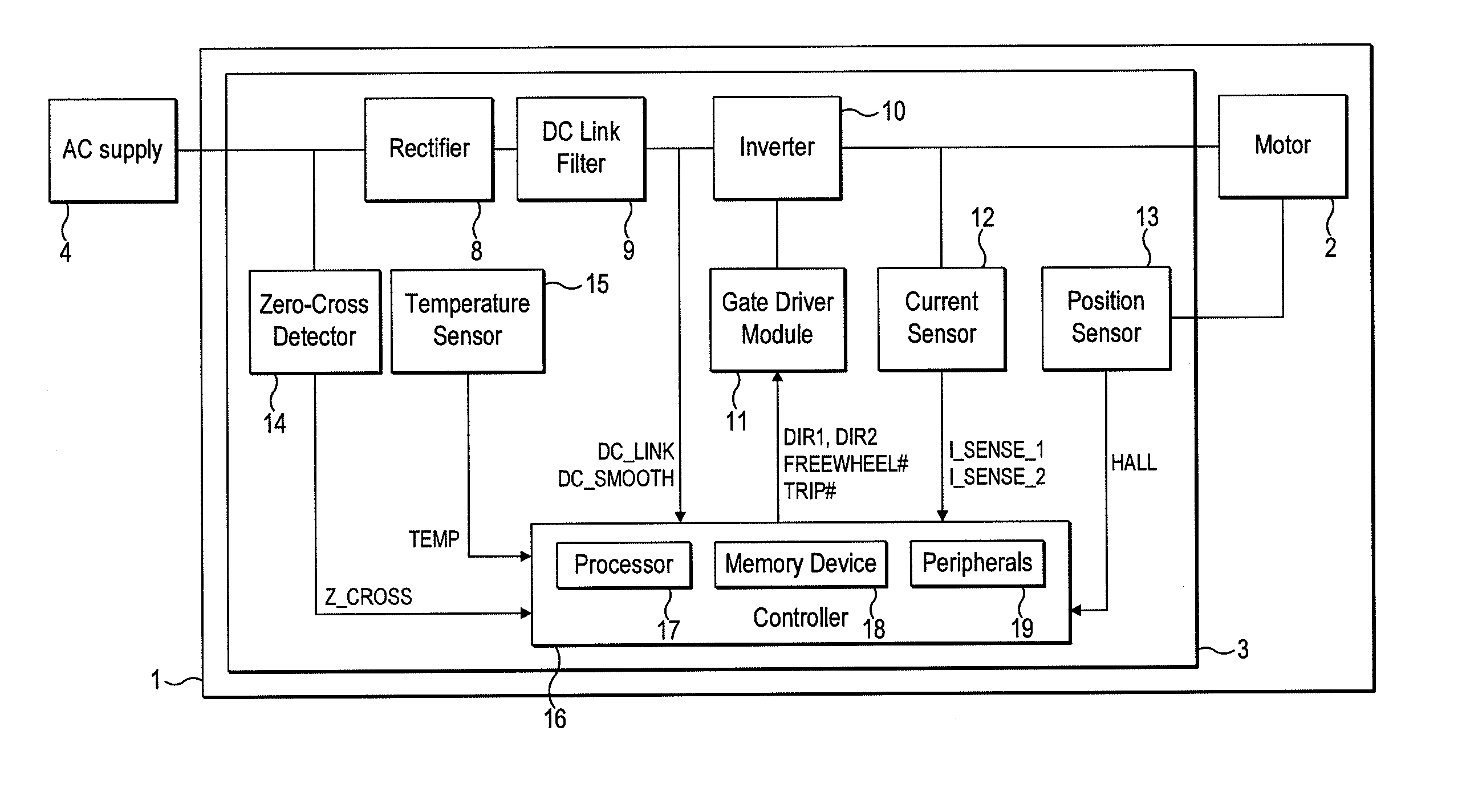
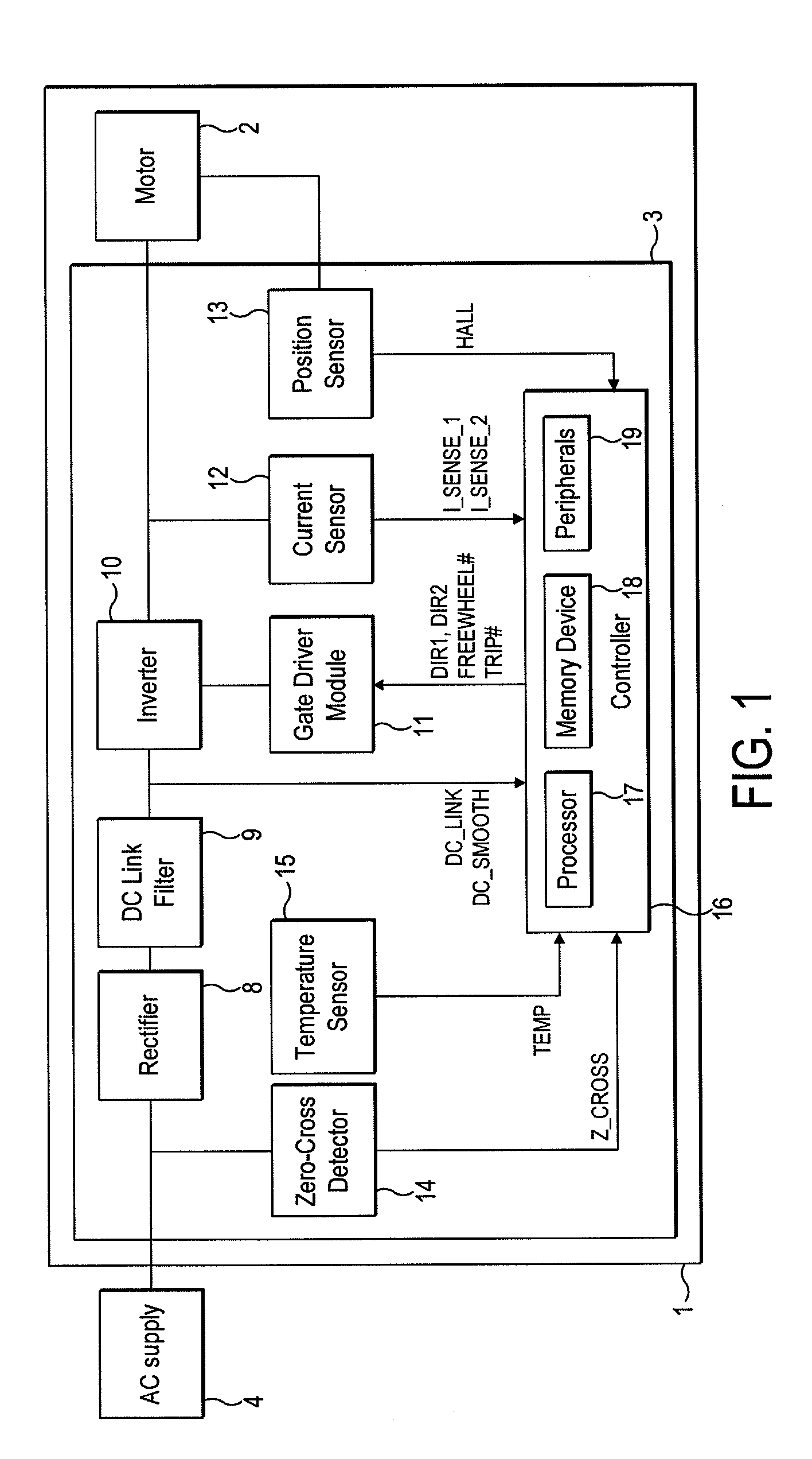
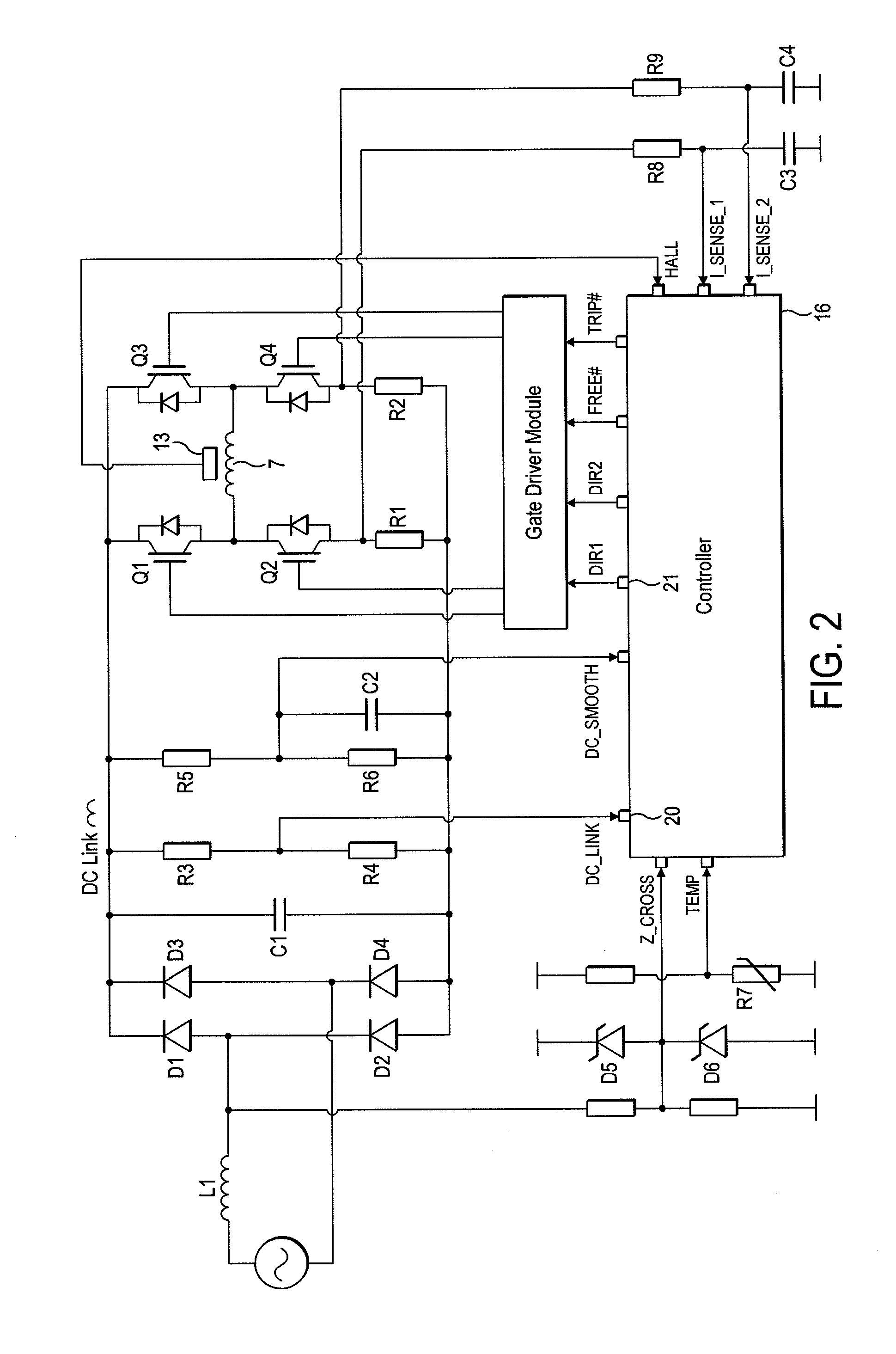
[0275]A particular embodiment of the motor system 1 will now be described by way of example only. Values for various hardware components of the motor system 1 are detailed in FIG. 19, while FIG. 20 lists various constants and thresholds employed by the controller 16. FIGS. 21 and 22 detail the flux-linkage characteristics of the link inductor L1 and the motor 2.

[0276]As illustrated in FIG. 23, the motor system 1 has seven modes of operation: Fault, Initialization, Stationary, Low-Speed Acceleration, Mid-Speed Acceleration, High-Speed Acceleration, and Running. Accordingly, in comparison to that previously described and illustrated in FIG. 8, the motor system 1 has one additional mode of operation.

[0277]Fault, Initialization, Stationary and Low-Speed Acceleration Modes are unchanged from that previously described. Mid-Speed Acceleration Mode corresponds to the previously-described High-Speed Acceleration Mode. Consequently, when operating in Mid-Speed Acceleration Mode, the controlle...


PUM


Abstract

A method of controlling a brushless motor that includes rectifying an alternating voltage to provide a rectified voltage, exciting a winding of the motor with the rectified voltage and freewheeling the winding when current in the winding exceeds a threshold. The winding is freewheeled for a freewheel period, which is updated in response to a zero-crossing in the alternating voltage. Additionally, a control system that implements the method, and a motor system that incorporates the control system.

Description

REFERENCE TO RELATED APPLICATIONS[0001]This application claims the priority of United Kingdom Application No. 1006397.2, filed Apr. 16, 2010, the entire contents of which are incorporated herein by reference.FIELD OF THE INVENTION[0002]The present invention relates to control of a brushless motor.BACKGROUND OF THE INVENTION[0003]A brushless motor generally includes a control system that controls the excitation of phase windings of the motor. The control system may employ a current control scheme in which a winding is excited until current in the winding exceeds a threshold. On exceeding the threshold, the control system freewheels the winding so as to allow current in the winding to decay. Freewheeling may continue until current in the winding decays to a lower threshold, at which point the winding is again excited. Alternatively, the control system may freewheel the winding for a fixed period of time, after which the winding is again excited.[0004]As the motor speed increases, the ...

Claims


Application Information

Patent Timeline
Patent Type & Authority Applications(United States)
IPC IPC(8): H02P6/14
CPCH02P6/002H02P2209/07H02P29/028H02P6/28H02P29/032H02P6/15H02P6/34H02P6/085
Inventor CHEN, YUCELIK, TUNCAYGREETHAM, STEPHEN
Owner DYSON TECH LTD
Why Eureka
Try Eureka