Motor control apparatus and electric appliance using the same

a technology of motor control and electric appliances, applied in the direction of motor/generator/converter stopper, dynamo-electric gear control, dynamo-electric converter control, etc., can solve problems such as complicated circuit arrangement, and achieve the effect of simplified motor control circuit arrangement and effective reduction of variation in motor power consumption

Inactive Publication Date: 2005-11-17
TOSHIBA TEC KK
View PDF15 Cites 7 Cited by
  • Summary
  • Abstract
  • Description
  • Claims
  • Application Information

AI Technical Summary

Benefits of technology

[0006] Accordingly, it is an object of the present invention to effectively decrease variation in a power consumption of motor, using a simplified motor control circuit arrangement even if impedance of windings among motors varies.

Problems solved by technology

According to this method, a circuit arrangement is complicated because detection of current and voltage is evitable.

Method used


Image

  • Motor control apparatus and electric appliance using the same
  • Motor control apparatus and electric appliance using the same
  • Motor control apparatus and electric appliance using the same

Examples


first embodiment

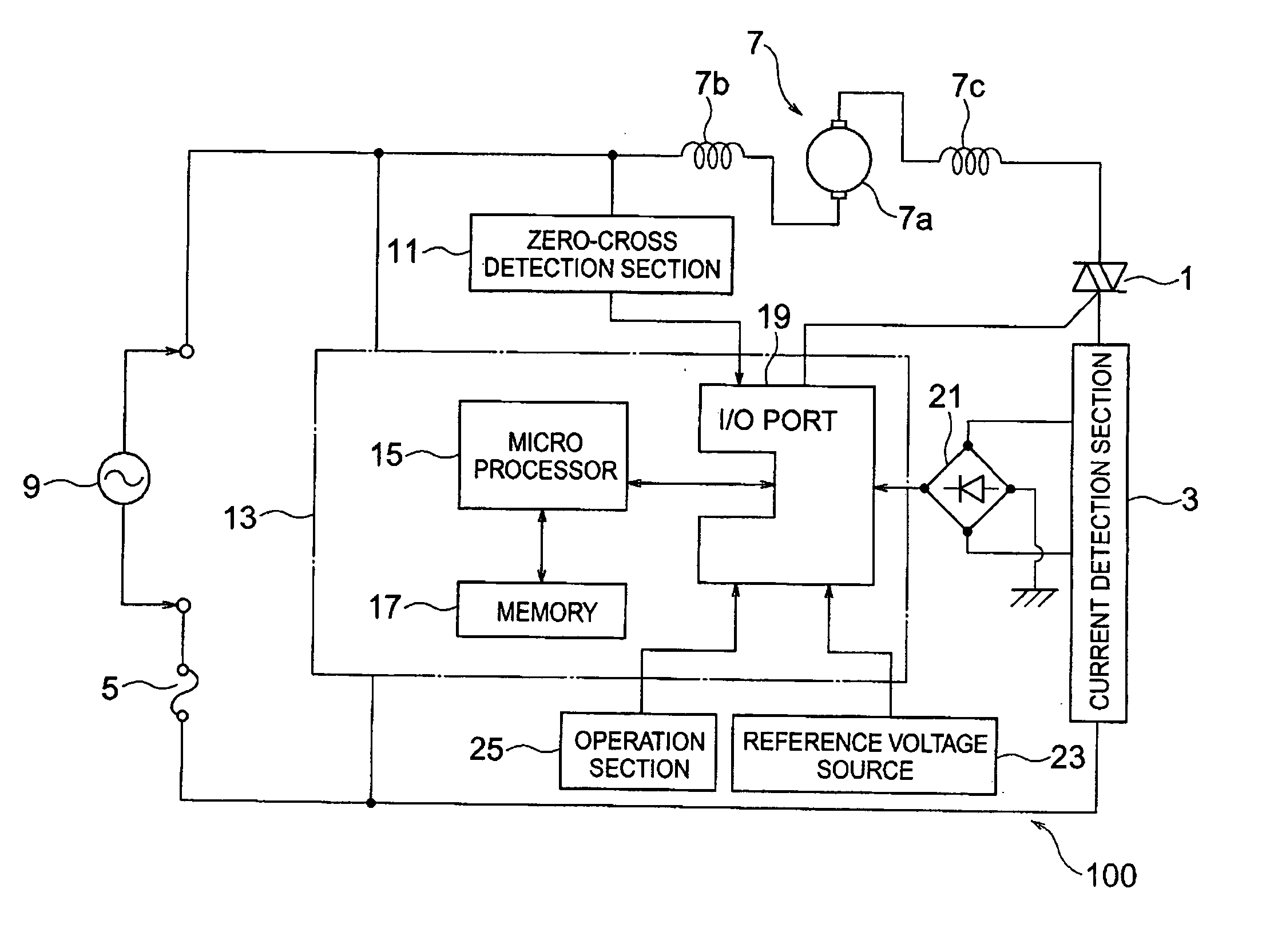
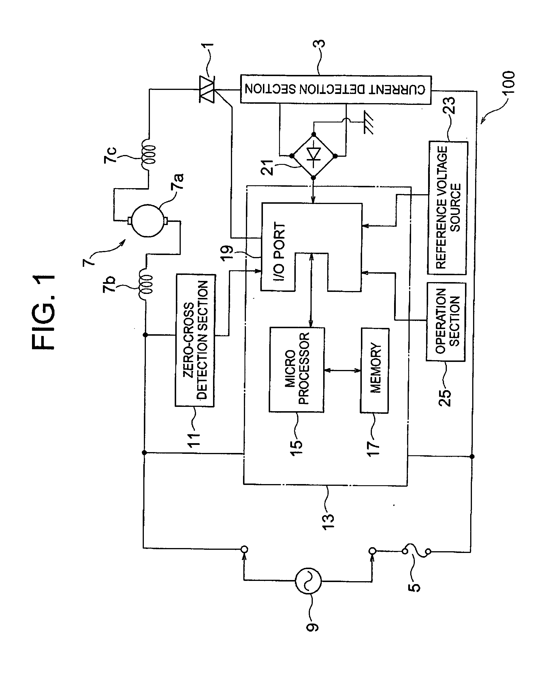
[0032] A first embodiment will be described with reference to FIG. 1. FIG. 1 shows a motor control apparatus 100. A switching element 1, e.g., bi-directional triode thyristor (hereinafter referred to as a TRIAC), a current detection section 3, a current fuse 5, and an AC driven type motor 7 are connected in series with a commercial AC power source 9. TRIAC 1 is activated with a trigger signal and may be replaced by other elements which are also driven with the trigger signal.

[0033] Motor 7 is a universal type motor which comprises an armature 7a with a rectifier, and field windings 7b, 7c. Current detection section 3 includes a current-transformer or a shunt-resistance, for example, for detecting a load current flowing through motor 7. A zero-crossing point of AC voltage applied to motor 7 is detected by a zero-cross detecting section 11.

[0034] As can be seen in FIG. 1, a control section 13 includes a microprocessor 15, a memory 17, and an I / O port 19. I / O port 19 is equipped with...

second embodiment

[0072] In this embodiment, an electric appliance, e.g., vacuum cleaner, to which the above-described first embodiment (motor control apparatus) is applied will be described.

[0073] As shown in FIG. 10, a vacuum cleaner 51 includes a lower case 53 whose upper surface is open, an upper case 55, a bumper 57 and a lid 59. The rear part of lower case 53 is closed by upper case 55. Bumper 57 is sandwiched between circumferential edges of lower case 53 and upper case 55 and is joined therewith. Lid 59 is swingably provided to the front part of lower case 53 to open and close the front part.

[0074] A bag-shaped filter 61 (hereinafter referred to as a filter) and an electric blower 63 are located in series inside vacuum cleaner 51. An airflow generated by blower 63 is led through filter 61 to separate dust from the airflow.

[0075] A caster (not shown) is provided on the rear surface of front part of cleaner 51 in forwarding direction and a pair of driven wheels 65 is respectively provided to...


PUM


Abstract

A microprocessor of the motor control apparatus acquires a zero-cross detection signal from a zero-cross detection section and a load current from a current detection section at a prescribed sampling period. The processor obtains a load current instant value every sampling period and a corresponding sine-functional value from a sine-functional value table to calculate a compensation value for the load current instant value. The processor also calculates a load current compensation total value by adding the compensation value by the predetermined number of times of sampling and compares the load current compensation total value with a load current reference value to obtain a difference therebetween. In response to the difference, an instruction value for delay time that determines the output timing of a trigger signal to a switching element is changed so that power consumption of the motor falls within a prescribed range.

Description

BACKGROUND OF THE INVENTION [0001] (1) Field of the Invention [0002] The present invention relates, in general, to a motor control apparatus and, in particular, to an apparatus which controls the operation of an AC driven type motor and an electric appliance which is equipped with such a motor control apparatus. [0003] (2) Description of the Related Art [0004] In an AC driven type motor, a power-control thereof is generally carried out based on a load current value that flows through the motor. However, due to the inductivity of windings of the motor, a phase difference between voltage and current occurs. In addition, impedance of windings varies among motors, respectively. Phenomena that power consumption varies among motors due to the phase difference described above can be observed even if amount of the load current flowing through respective motors is the same. Therefore, it is necessary to regulate variation in the power consumption of motors even a prescribed same voltage is a...

Claims


Application Information

Patent Timeline
Patent Type & Authority Applications(United States)
IPC IPC(8): H02P21/14A47L9/28H02P21/22H02P23/00H02P23/14H02P23/26H02P25/10H02P25/14
CPCH02P25/14H02P1/00
Inventor KUSHIDA, HIROYUKISAKURAI, OSAMUISHIZAWA, AKIHIRO
Owner TOSHIBA TEC KK
Why Eureka
Try Eureka