Magnetic resonance apparatus

Inactive Publication Date: 2013-09-12
SIEMENS HEALTHCARE GMBH
View PDF8 Cites 11 Cited by
  • Summary
  • Abstract
  • Description
  • Claims
  • Application Information

AI Technical Summary

Benefits of technology

[0015]There can further be provision for the housing unit to have at least one attachment unit for attaching the ho

Problems solved by technology

During operation, magnetic resonance apparatuses generate high levels of noise, which have an unpleasant effect on a patient occupying an imaging area of the magnetic resonance apparatus for an examination.
These high levels of operating noise are generated within

Method used


Image

  • Magnetic resonance apparatus
  • Magnetic resonance apparatus
  • Magnetic resonance apparatus

Examples


Embodiment Construction

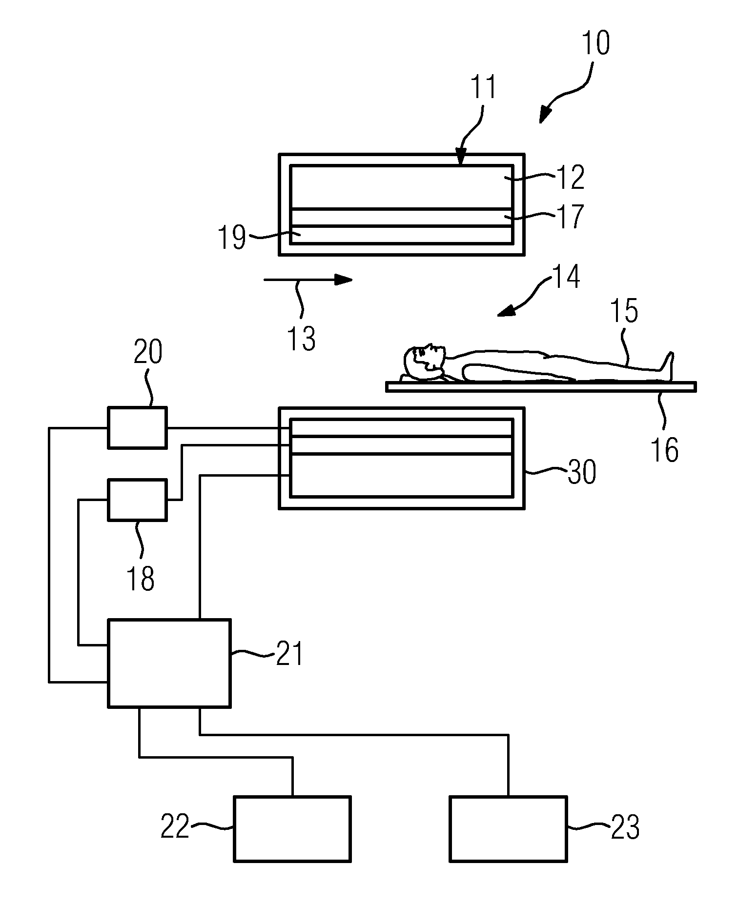
[0020]FIG. 1 shows a schematic of a disclosed magnetic resonance apparatus. The magnetic resonance apparatus 10 comprises a magnet unit 11 with a main magnet 12 for generating a strong and constant main magnetic field 13. In addition the magnetic resonance apparatus 10 has a cylindrical receiving area 14 for receiving a patient 15, wherein the receiving area 14 is surrounded in a circumferential direction by the magnet unit 11. The patient 15 can be pushed by a patient couch 16 of the magnetic resonance apparatus 10 into the receiving area 14. For this purpose the patient couch 16 is disposed so that it is able to be moved within the magnetic resonance apparatus 10. Furthermore the magnetic resonance apparatus 10 has a housing unit 30 surrounding the magnet unit 11.

[0021]The magnet unit 11 also has a gradient coil 17 for generating magnetic field gradients which are used for local encoding during imaging. The gradient coil 17 is controlled by a gradient control unit 18. Furthermore ...


PUM


Abstract

A magnetic resonance apparatus is proposed. The magnetic resonance apparatus has a magnet unit and a housing unit. The housing unit has a housing shell unit. The housing shell unit surrounds the magnet unit. The housing shell unit at least partly has a flexible material. Effective noise protection for operation of the magnetic resonance apparatus is provided.

Description

CROSS REFERENCE TO RELATED APPLICATIONS[0001]This application claims priority of German application No. 10 2011 082 411.1 filed Sep. 9, 2011, which is incorporated by reference herein in its entirety.FIELD OF INVENTION[0002]The present application relates to a magnetic resonance apparatus with a magnet unit and the housing unit with a housing shell unit surrounding the magnet unit.BACKGROUND OF INVENTION[0003]During operation, magnetic resonance apparatuses generate high levels of noise, which have an unpleasant effect on a patient occupying an imaging area of the magnetic resonance apparatus for an examination. These high levels of operating noise are generated within a magnet unit of the magnetic resonance apparatus. Sound waves are transmitted in such cases from the gradient system of the magnet unit to a main magnet of the magnet unit. From this main magnet the noise is transferred to a housing unit of the magnetic resonance apparatus and from there it is emitted into a space su...

Claims


Application Information

Patent Timeline
IPC IPC(8): G01R33/38
CPCG01R33/38G01R33/28A61B5/055G01R33/30G01R33/34A61B5/748
Inventor DIETZ, PETERSTEIN, ANNETTE
Owner SIEMENS HEALTHCARE GMBH
Why Eureka
Try Eureka