
Method and device for driving an OLED panel

a technology of organic light and diodes, applied in the direction of electric digital data processing, instruments, computing, etc., can solve the problems of generating the problem of dither noise and flashing of frame rate control (frc), and reducing the resolution of real gray levels

Inactive Publication Date: 2013-09-12
CHUNGHWA PICTURE TUBES LTD
View PDF4 Cites 7 Cited by
  • Summary
  • Abstract
  • Description
  • Claims
  • Application Information

AI Technical Summary

Benefits of technology

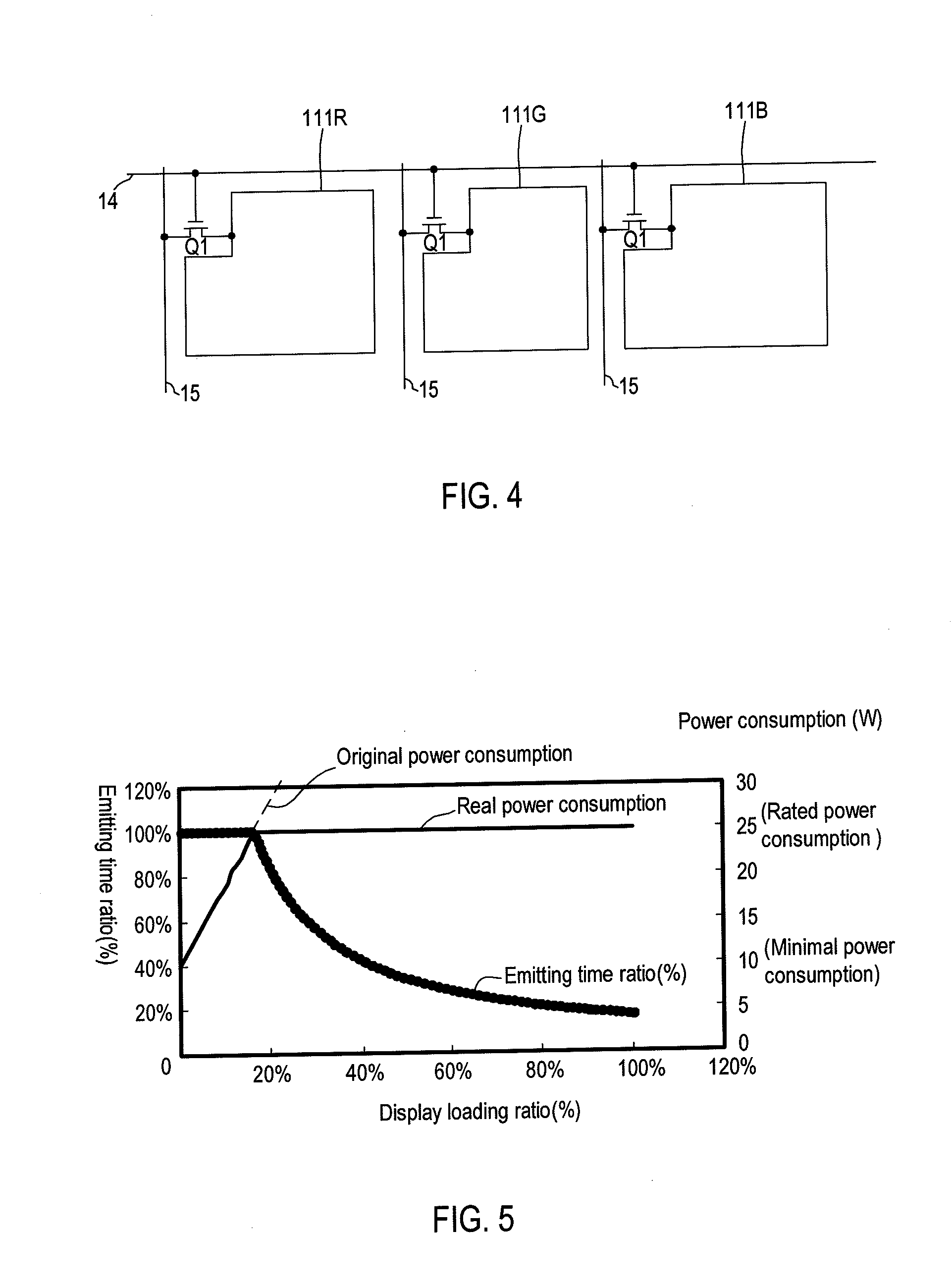
The present invention relates to a method for controlling the power consumption of an OLED panel by controlling the emitting time. This method includes steps of calculating the display loading ratio, finding the emitting time ratio in a power control look-up table, and inputting the emitting time signal to the OLED panel. This method can improve the lifetime of the OLED panel and maintain the resolution of the same gray-level. It can also indirectly improve the quality of motion blur image without causing problems of dither noise and flash of frame rate control.

Problems solved by technology

However, disadvantages of the above-mentioned solution are to decrease resolution of the real gray-level and to generate the problem of the dither noise and the flash of frame rate control (FRC).

Method used


Image

  • Method and device for driving an OLED panel
  • Method and device for driving an OLED panel
  • Method and device for driving an OLED panel

Examples


Embodiment Construction

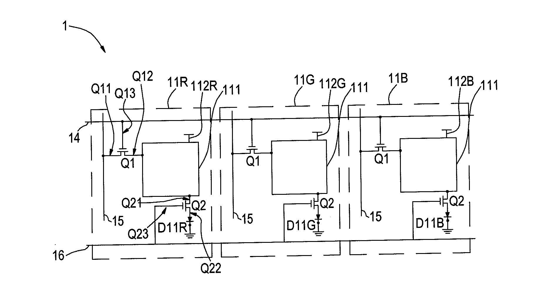
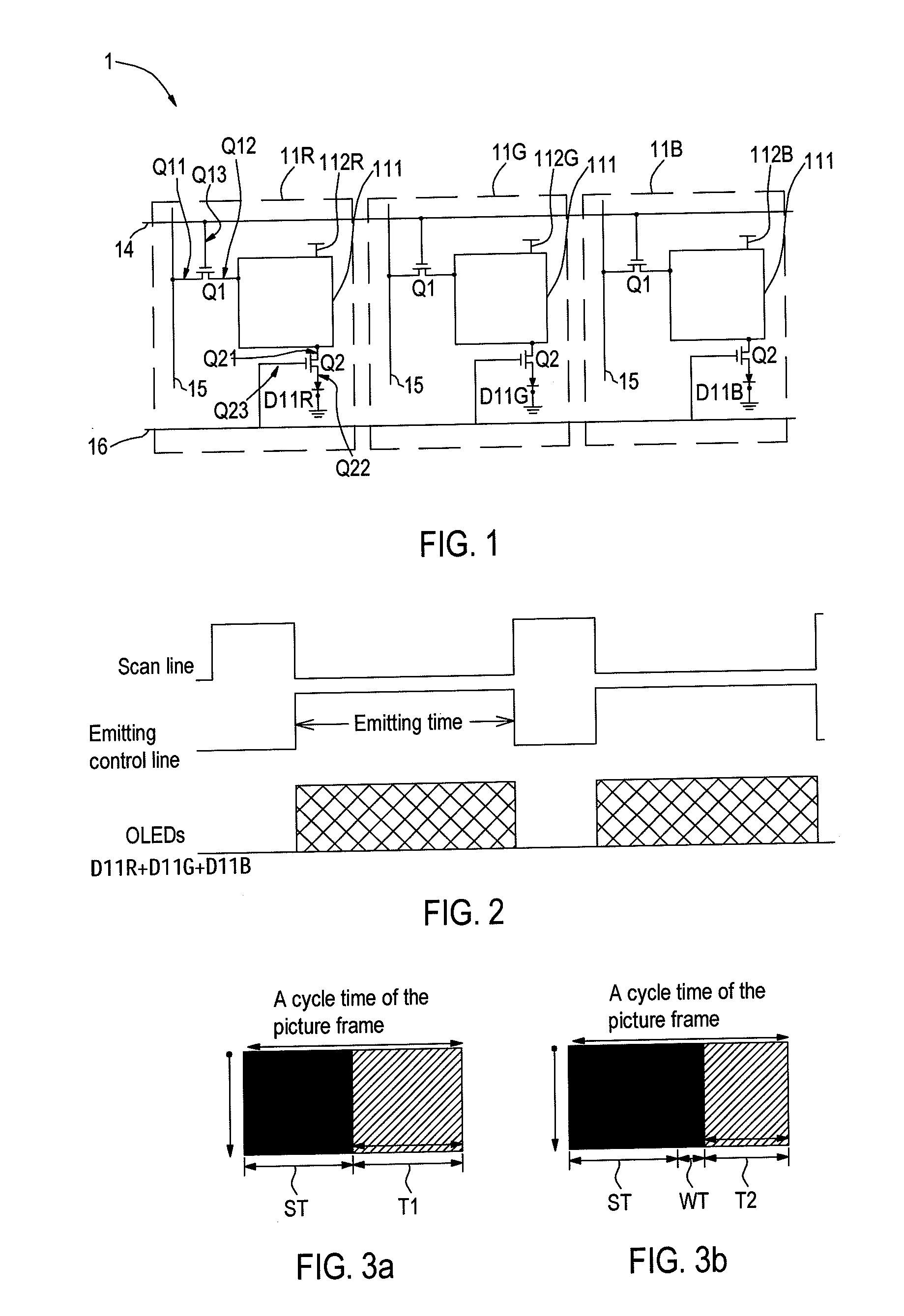
[0024]FIG. 1 is a circuit diagram of an organic light emitting diode (OLED) panel according to an embodiment of the present invention. The OLED panel 1 includes a plurality of data lines 15, scan lines 14, emitting control lines 16, red regions 11R, green regions 11G and blue regions 11B. In order to be easily described, FIG. 1 only shows three data lines 15, one scan line 14, one emitting control line 16, one red region 11R, one green region 11G and one blue region 11B. Each region (i.e., pixel region) of the red regions 11R, green regions 11G and blue regions 11B includes a pixel circuit 111, a first thin film transistor (TFT) Q1, a second thin film transistor (TFT) Q2 and an organic light emitting diode (OLED) D11R, D11G or D11B. A first end Q11 of the first TFT Q1 of each region is electrically connected to the corresponding data line 15, a second end Q12 is electrically connected to the pixel circuit 111, and a control end Q13 is electrically connected to the scan line 14. The ...


PUM


Abstract

A method for driving an OLED panel includes the following steps. An image signal is inputted to a power control unit, wherein the power control unit includes a calculator and a power control look-up table. A display loading ratio is calculated by the calculator according to the image signal, wherein the power control unit can find an emitting time ratio by the power control look-up table corresponding to the display loading ratio, the emitting time ratio can be transformed to an emitting time signal, and the emitting time signal can be inputted to the OLED panel so as to control the power consumption of the OLED panel.

Description

CROSS-REFERENCE TO RELATED APPLICATION[0001]This application claims the benefit of Taiwan Patent Application No. 101107442, filed on Mar. 6, 2012, which is hereby incorporated by reference for all purposes as if fully set forth herein.BACKGROUND OF THE INVENTION[0002]1. Field of Invention[0003]This invention relates to a method and a device for driving an organic light emitting diode (OLED) panel, and more particularly to a driving method and a driving device for controlling an emitting time of an OLED panel.[0004]2. Related Art[0005]An organic light emitting diode (OLED) panel is better than other flat panel, and has many advantages of lower power consumption, high brightness, easy manufacture, etc., for example.[0006]When the OLED panel is applied to a portable or handheld electronic product, such as cell phone, digital camera, digital camcorder, etc., components of the electronic product generally has an important requirement of property, i.e. lower power consumption. Thus, a ven...

Claims


Application Information

Patent Timeline
Patent Type & Authority Applications(United States)
IPC IPC(8): G06F3/038
CPCG06F3/038G09G3/3233G09G2320/064G09G2330/021G09G2360/16
Inventor CHIU, CHUN-CHIEHCHANG, SHIH-MENGCHEN, CHIEN-HUNG
Owner CHUNGHWA PICTURE TUBES LTD
Learn More