Image capture apparatus

a technology of image capture and apparatus, applied in the field of image capture apparatus, can solve the problems of deviation between the focal position, focus detection error, and image shift between two images

Active Publication Date: 2013-09-12
CANON KK
View PDF3 Cites 44 Cited by
  • Summary
  • Abstract
  • Description
  • Claims
  • Application Information

AI Technical Summary

Benefits of technology

[0011]The present invention has been achieved in light of the above-described problems, and enables high-precision correction of focus detection error when performing focus detection with a phase difference detection method using an image sensor in which image forming pixels and focus detecting pixels are arranged on an image sensing plane.

Problems solved by technology

However, due to offset (misalignment in the optical axis direction) in the spatial arrangement of the focus detection means, optical aberration of the imaging optical system, and problems unique to the photoelectric conversion element for focus detection, there are cases where the amount of image shift between two images is not zero even when in the in-focus state.
In such cases, focus detection error arises if the detected image shift amount is converted into the defocus amount as is.
This results in deviation between the focal position at which imaging performance is the best and the focal position calculated based on focus detection signals.
However, since pupil division is performed with very small microlenses and photoelectric conversion portions in this technology, there are cases where luminous flux is scattered in pixels and electrical crosstalk occurs between photoelectric conversion portions.
Accordingly, even when in the in-focus state, there are cases where the image shift amount between two images is not zero, but rather predetermined image shift error arises.
Since this image shift error arises due to individual pixel characteristics, it is difficult to resolve with the methods disclosed in the aforementioned prior art documents.
Also, the error in Japanese Patent Laid-Open No. 62-189415 and Japanese Patent Laid-Open No. 11-218764 is caused by optical aberration of the imaging optical system.

Method used


Image

  • Image capture apparatus
  • Image capture apparatus
  • Image capture apparatus

Examples


first embodiment

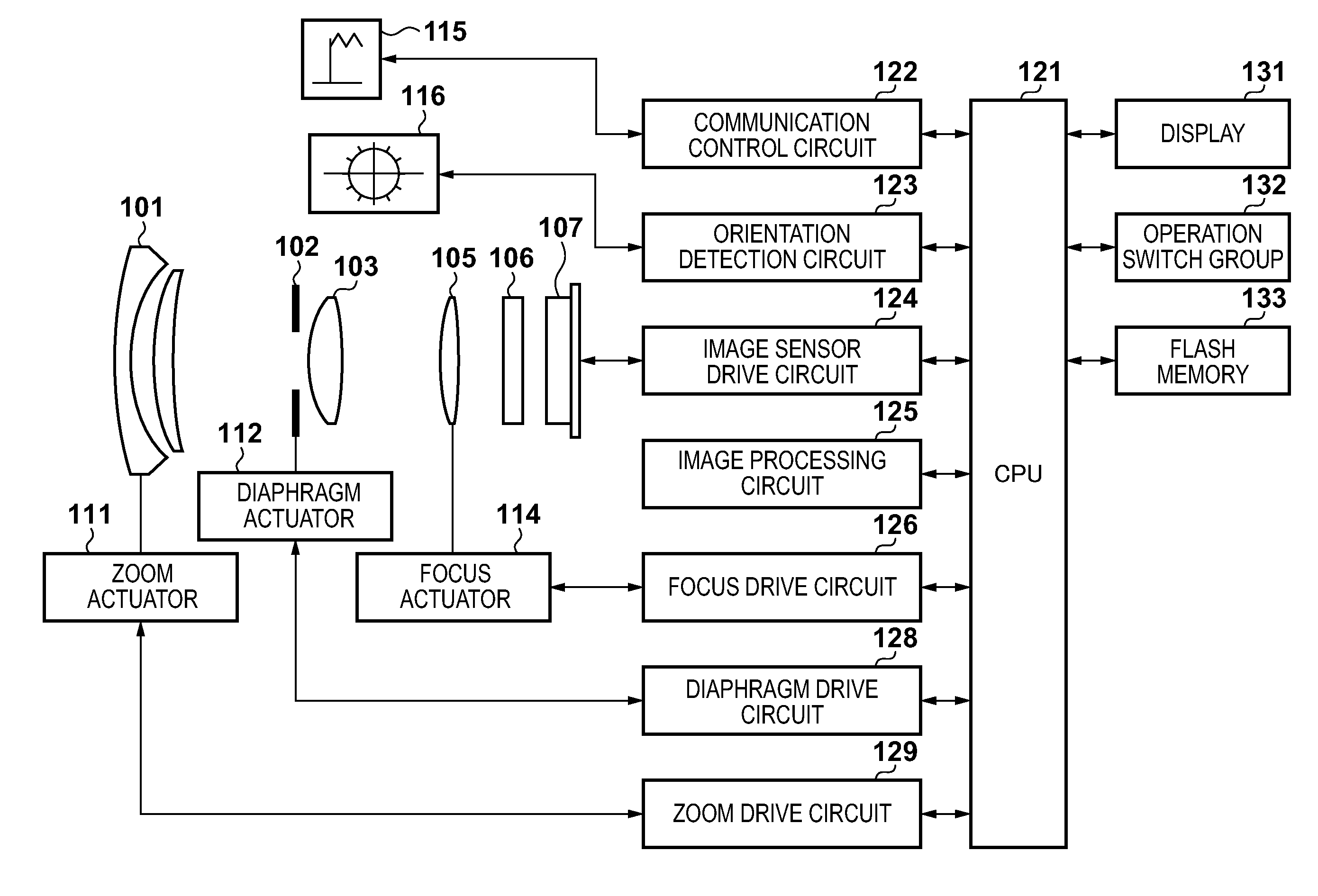
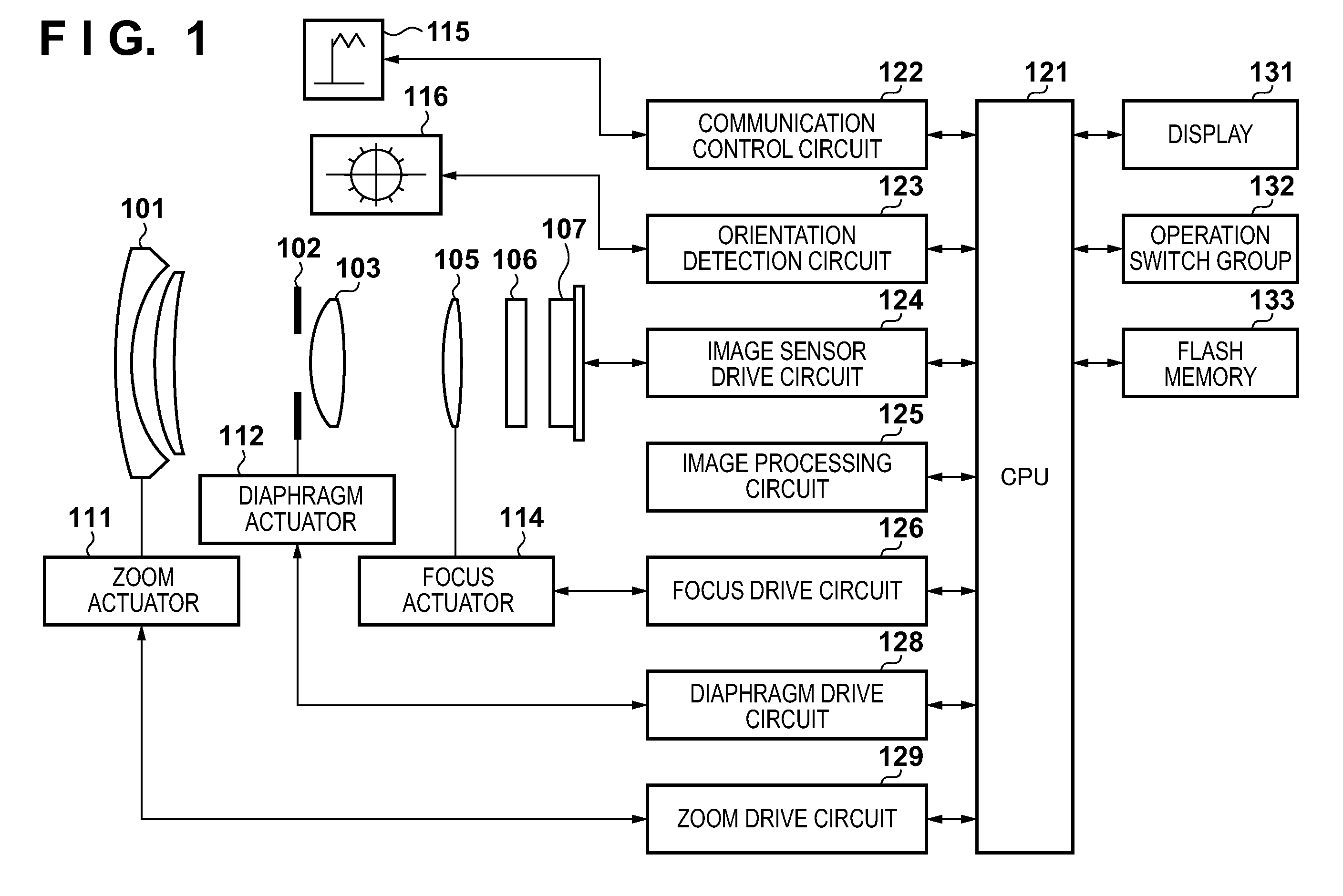
[0033]FIG. 1 is a diagram showing a configuration of an image capture apparatus according to a first embodiment of the present invention. The image capture apparatus of the present embodiment is an electronic camera in which an imaging optical system and a camera body that has an image sensor are integrated, and the image capture apparatus can record moving images and still images. In FIG. 1, reference sign 101 denotes a first lens group that is arranged at the front of the imaging optical system (image forming optical system) and is held so as to be capable of moving in the optical axis direction. Reference sign 102 denotes a diaphragm whose opening diameter is adjusted so as to make it possible to adjust the F-number of the imaging optical system and adjust the amount of light during imaging, and also functions as a shutter for adjusting the exposure time during still image capturing. Reference sign 103 denotes a second lens group. The diaphragm 102 and the second lens group 103 a...

second embodiment

[0101]In the first embodiment, error correction using a predetermined amount is applied to the image shift amount between two images that is subjected to a phase difference operation. In a second embodiment described below, the image shift amount is transformed (converted) into a defocus amount, and then correction is applied to the defocus amount.

[0102]The second embodiment differs from the first embodiment only with respect to the error correction step in the focus detection subroutine, and since the configuration of the image capture apparatus and the main flow for controlling operations of the image capture apparatus are substantially the same as those in the first embodiment, only the differences will be described below.

[0103]FIG. 15 is a flowchart of a focus detection subroutine according to the second embodiment. When there is a jump from step S111 of the main flow to step S211 of this subroutine, the procedure moves to step S212 in which an object pattern is recognized based...

third embodiment

[0109]In the first and second embodiments, correction is applied to the result of performing focus adjustment on the main object that is the target of focus adjustment. In a third embodiment described below, focus state information regarding the entire area of a captured image, that is to say, a defocus map, is created.

[0110]The third embodiment differs from the first embodiment only with respect to the focus detection subroutine, and since the configuration of the image capture apparatus and the main flow for controlling operations of the image capture apparatus are substantially the same as those in the first embodiment, only the differences will be described below.

[0111]FIG. 16 is a flowchart of a focus detection subroutine according to the third embodiment. When there is a jump from step S111 of the main flow to step S311 of this subroutine, the procedure moves to step S312 in which an object pattern is recognized based on the preview image, facial image detection is performed, ...


PUM


Abstract

An image capture apparatus includes: an image sensor having a plurality of pixels that photoelectrically convert an object image formed by an imaging optical system, each of the pixels having one microlens and a photoelectric conversion portion that has been divided into a plurality of portions; a focus detection unit configured to correct an image shift amount detected with a phase difference detection method using focus detection signal arrays of two images obtained by the photoelectric conversion portions divided into a plurality of portions; and a controller that calculates information corresponding to a movement amount of a lens of the imaging optical system based on the image shift amount detected and corrected by the focus detection unit, and controls movement of the lens of the imaging optical system.

Description

BACKGROUND OF THE INVENTION[0001]1. Field of the Invention[0002]The present invention relates to an image capture apparatus that performs focus detection with a phase difference detection method using an image sensor in which image forming pixels and focus detecting pixels are arranged on an image sensing plane.[0003]2. Description of the Related Art[0004]Technology has been proposed for performing high-speed and high-precision focus detection using a phase-difference focus detection means in an image capture apparatus that has an imaging optical system and an image sensor. In phase-difference focus detection technology, luminous flux that exits the imaging optical system is divided into at least two areas by a pupil division means, and a pair of focus detection signal arrays of two images are obtained by photoelectrically converting the luminous flux in the areas. A so-called defocus amount, which is the amount of defocus of a predicted focal plane, is detected based the amount of ...

Claims


Application Information

Patent Timeline
Patent Type & Authority Applications(United States)
IPC IPC(8): H04N5/232
CPCH04N5/23212H04N5/3696H04N23/672H04N23/61H04N25/61H04N25/704H04N25/134
Inventor ONUKI, ICHIRONISHIO, AKIHIROFUKUDA, KOICHITAMAKI, YOSHIHITOYOSHIMURA, YUKI
Owner CANON KK
Why Eureka
Try Eureka