
Camera Module

a technology of camera module and camera body, which is applied in the field of camera module, can solve the problems of deteriorating mechanical reliability of the camera module, inflow of foreign substances between, and reducing the adhesive strength, so as to prevent stable adhesive strength, and the effect of preventing the tilting of the cover glass

Active Publication Date: 2013-09-12
LG INNOTEK CO LTD
View PDF4 Cites 17 Cited by
  • Summary
  • Abstract
  • Description
  • Claims
  • Application Information

AI Technical Summary

Benefits of technology

The camera module in this invention expels air between the IR filter and image sensor through a hole, which prevents the cover glass from tilting and ensures stable adhesion with the IR filter. This increases the reliability of the camera module and prevents malfunctions.

Problems solved by technology

Further, a reduction in adhesive strength between the IR filter 3 and the cover glass 4 may deteriorate mechanical reliability of the camera module, and may cause inflow of foreign substances between the image sensor 2 and the IR filter 3 because of the opened sealing.

Method used


Image

  • Camera Module
  • Camera Module
  • Camera Module

Examples


first embodiment

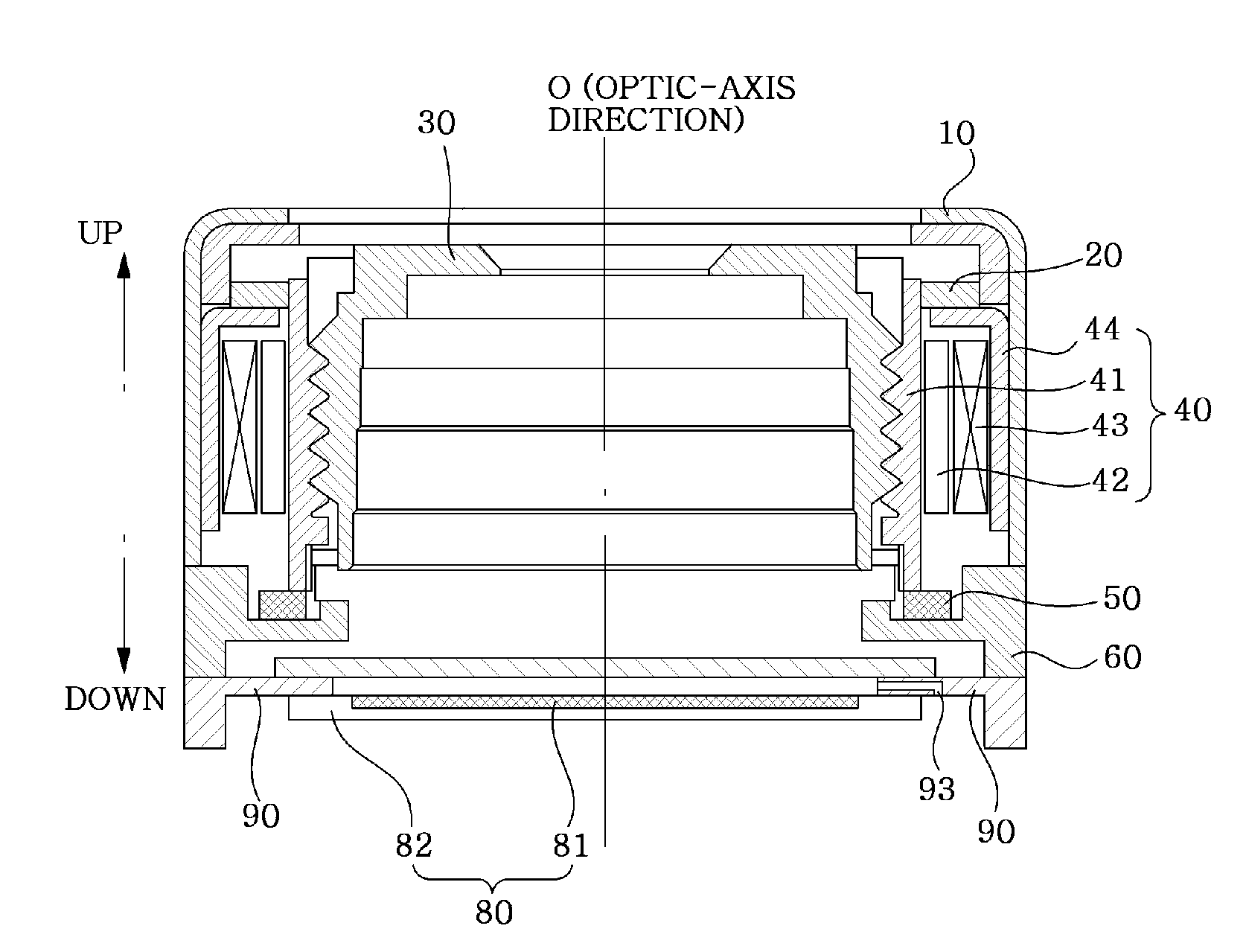
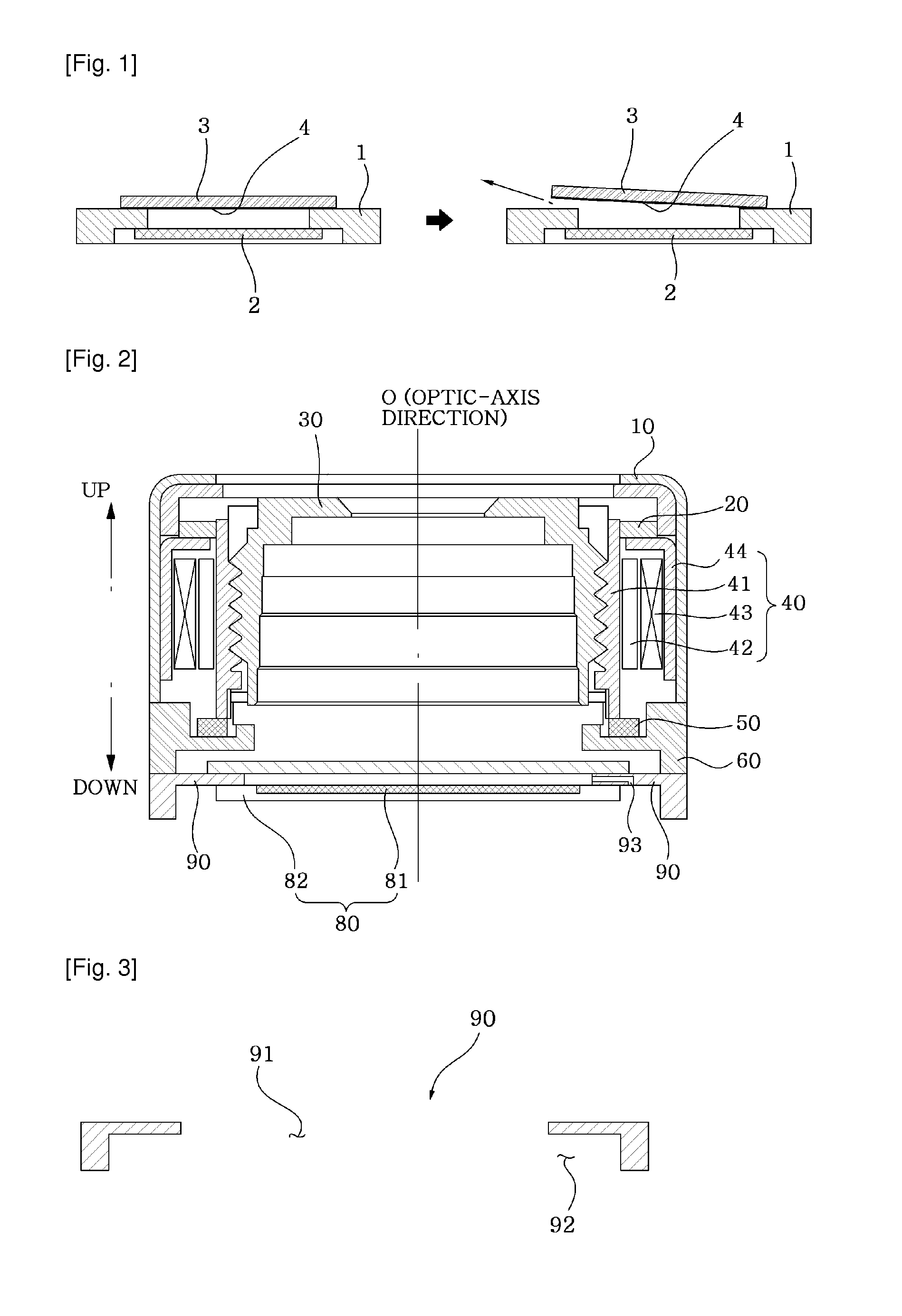
[0037]FIG. 2 is a sectional view illustrating a camera module in accordance with the present invention, and FIG. 3 is a sectional view illustrating a first PCB of FIG. 2.

[0038]As shown in FIG. 2, the camera module of the present invention includes a casing 10, an upper elastic member 20, a lens barrel 30, an actuator 40, a lower elastic member 50, a frame 60, an IR filter 70, an image sensor 80, and a first PCB 90.

[0039]In the drawing of this invention, the camera module having the actuator 40 is shown. The actuator 40 serves as a moving part for moving the lens barrel 30 in a direction of an optic axis 0 for the purpose of auto focusing. However, the present invention may be applied to a camera module having no actuator. In the case of the camera module having no actuator, the lens barrel 30 instead of a bobbin 41 is fastened to a holder in a threaded manner. In the present invention, the bobbin 41 serves as the holder for holding the lens barrel 30.

[0040]The casing 10 takes a shap...

second embodiment

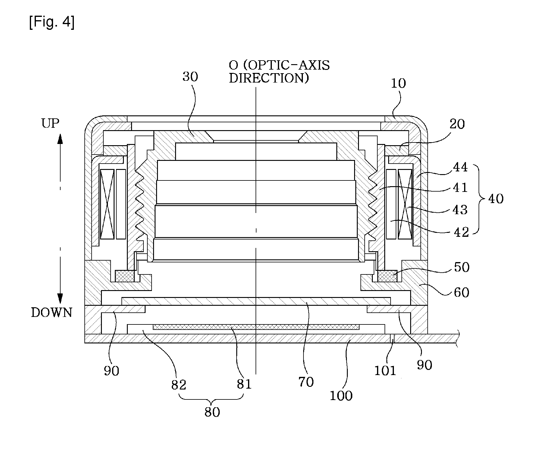
[0069]FIG. 4 is a sectional view illustrating a camera module in accordance with the present invention.

[0070]A general construction of the camera module of FIG. 4 remains the same as the camera module of FIG. 2 except that a lower surface of an image sensor 80 is attached to an upper surface of a second PCB 100 and a second through hole 101 is formed through the second PCB 100. Thus, the construction and effect of the camera module shown in FIG. 2 will be omitted below for the convenience of description.

[0071]As shown in FIG. 4, the second PCB 100 is a flexible printed circuit board (FPCB) that is positioned under a first PCB 90 and extends to an outside of the first PCB 90. A connector (not shown) connected to other devices may be attached to the upper surface of the second PCB 100 extending to the outside of the first PCB 90.

[0072]In the second embodiment of the present invention, the second through hole 101 is formed through the second PCB 100 to make a cavity 92 communicate with...


PUM


Abstract

Disclosed is a camera module, the module including an IR filter for filtering infrared rays, an image sensor located under the IR filter to convert an incident optic image into an electric signal, a first PCB having a window to permit passage of the optic image and a cavity extending downwards from the window to accommodate the image sensor, a predetermined portion of an upper portion of the cavity being electrically connected to a predetermined portion of an upper surface of the image sensor, and a first through hole taking a shape of a pipe that is connected at one end thereof to the window and connected at the other end to the cavity, the first through hole serving as a path for discharging air between the IR filter and the image sensor.

Description

TECHNICAL FIELD[0001]The present invention relates to a camera module.BACKGROUND ART[0002]Recently, there is an increasing demand for a small-sized camera module used for an image input device for an information terminal such as a surveillance camera or a video tape recorder, as well as a variety of multimedia fields including a notebook-sized personal computer, a camera phone, a personal digital assistant (PDA), a smart-phone, and a toy.[0003]As a pixel size of a sensor applied to the camera module becomes smaller and smaller and a height of the module is reduced, there is an urgent demand for development of a mounting structure for preventing inflow of foreign substances and achieving mechanical reliability of the camera module against a tilt or shift of an optic axis of a lens.[0004]FIG. 1 is a view illustrating an image sensor and an IR (Infrared) filter attached to a printed circuit board (PCB) according to the prior art.[0005]As shown in FIG. 1, according to the prior art, the...

Claims


Application Information

Patent Timeline
Patent Type & Authority Applications(United States)
IPC IPC(8): H04N5/225
CPCH01L27/14618H04N5/2253H04N5/2257H04N5/2254H01L2924/0002H04N23/57H04N23/55H01L2924/00G03B17/02G03B30/00G02B7/021H04N23/54
Inventor RYU, YOUNGJUN
Owner LG INNOTEK CO LTD
Features
  • Generate Ideas
  • Intellectual Property
  • Life Sciences
  • Materials
  • Tech Scout
  • Unparalleled Data Quality
  • Higher Quality Content
  • 60% Fewer Hallucinations
Learn More