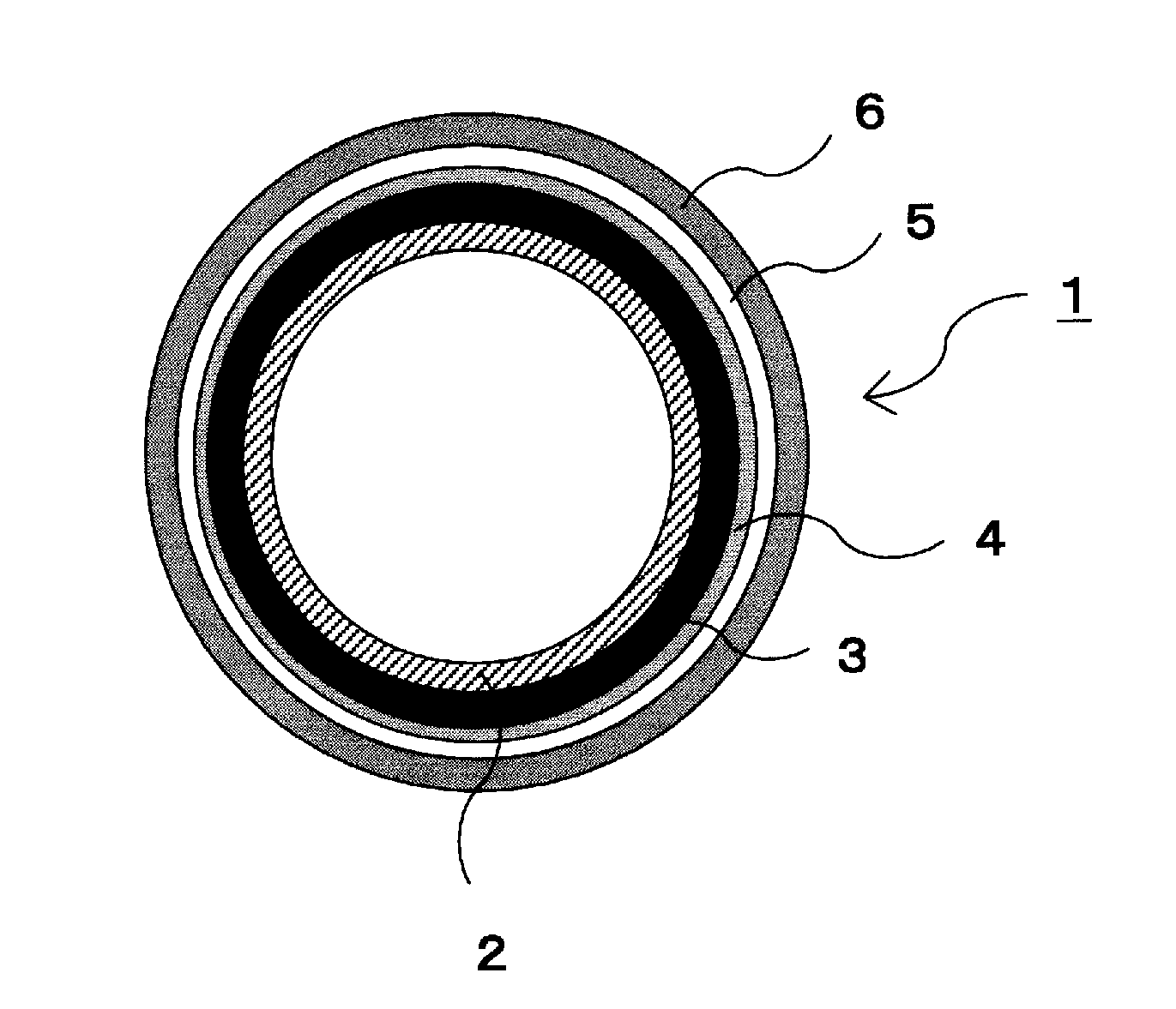
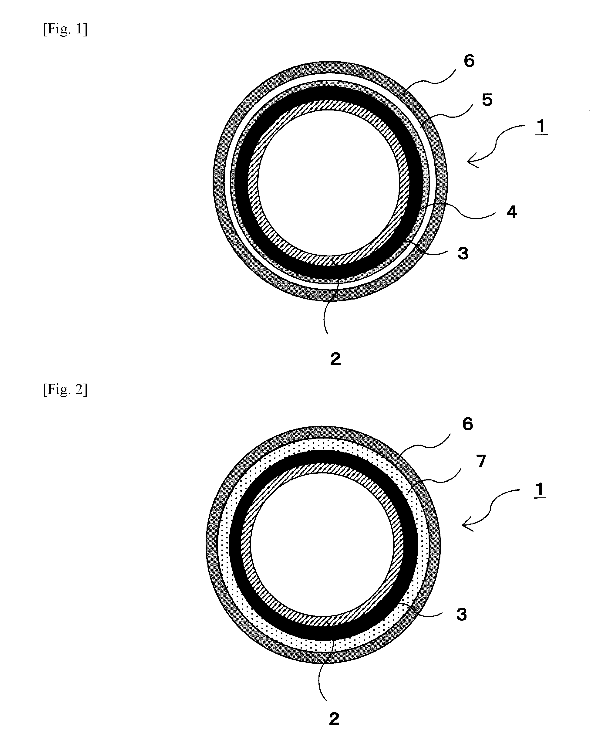
Silicone rubber-fluororesin laminate
a fluororesin laminate and silicone rubber technology, applied in the field of silicone rubberfluororesin laminates, can solve the problems of poor adhesion of the thin tubular fluororesin with an elastic layer, difficult inner surface treatment of thin tubular fluororesin, poor hot adhesion and adhesion after long-term heating tests, etc., to achieve stable adhesive strength and increase the adhesion between silicone rubber and fluororesin in hot state
- Summary
- Abstract
- Description
- Claims
- Application Information
AI Technical Summary
Benefits of technology
Problems solved by technology
Method used
Image

Examples
example 1
[0050]A cylindrical nickel belt having an inner diameter of 40 mm, a thickness of 30 and a length of 410 mm used as a substrate was coated with a silane based adhesive for elastic layers (DY39-042, produced by Dow Corning Toray Co., Ltd.). Further, silicone rubber (X34-2008, produced by Shin-Etsu Silicone Co., Ltd.) was applied thereon using a dispenser to form a silicone rubber layer having a thickness of 100 μm. The silicone rubber layer was vulcanization-molded by heat treatment.
[0051]The silicone rubber layer was coated by spraying with the following epoxy resin-containing silane based primer. The resulting product was allowed to stand for several minutes at ordinary temperature to volatilize the solvent, thereby forming an epoxy resin-containing silane based primer layer having a thickness of 2 μm.
Cresol novolak type epoxy resin2.91parts by weight (46.9 wt %)(N-695, produced by DIC)3-aminopropyltriethoxysilane3.00parts by weight (48.3 wt %)Vinyltriethoxysilane0.30parts by weigh...
example 2
[0053]In Example 1, among the components of the epoxy resin-containing silane based primer as the lower layer, the amount of cresol novolak type epoxy resin was changed to 4.37 parts by weight (55.2 wt %), the amount of 3-aminopropyltriethoxysilane was changed to 3.3 parts by weight (41.7 wt %), the amount of vinyltriethoxysilane was changed to 0.25 parts by weight (3.2 wt %), and the amount of methyl ethyl ketone was changed to 4.64 parts by weight.
example 3
[0054]In Example 1, among the components of the epoxy resin-containing silane based primer as the lower layer, the amount of cresol novolak type epoxy resin was changed to 5.34 parts by weight (66.8 wt %), the amount of 3-aminopropyltriethoxysilane was changed to 2.5 parts by weight (31.3 wt %), the amount of vinyltriethoxysilane was changed to 0.15 parts by weight (1.9 wt %), and the amount of methyl ethyl ketone was changed to 5.67 parts by weight.
PUM
| Property | Measurement | Unit |
|---|---|---|
| surface roughness Rz | aaaaa | aaaaa |
| thickness | aaaaa | aaaaa |
| thickness | aaaaa | aaaaa |
Abstract
Description
Claims
Application Information
 - Generate Ideas
- Intellectual Property
- Life Sciences
- Materials
- Tech Scout
- Unparalleled Data Quality
- Higher Quality Content
- 60% Fewer Hallucinations
Browse by: Latest US Patents, China's latest patents, Technical Efficacy Thesaurus, Application Domain, Technology Topic, Popular Technical Reports.
© 2025 PatSnap. All rights reserved.Legal|Privacy policy|Modern Slavery Act Transparency Statement|Sitemap|About US| Contact US: help@patsnap.com