Electronic device
a technology of electronic devices and backplanes, applied in the direction of cooling/ventilation/heating modifications, circuit arrangements on insulating boards, support structure mounting, etc., can solve the problems of disadvantageous power efficiency of feed system and installation area within the circuit board unit, and achieve the effect of suppressing heat generation of the backplane, wide ensuring the ventilator of the backplane, and reducing the size of the backplan
- Summary
- Abstract
- Description
- Claims
- Application Information
AI Technical Summary
Benefits of technology
Problems solved by technology
Method used
Image

Examples
first embodiment
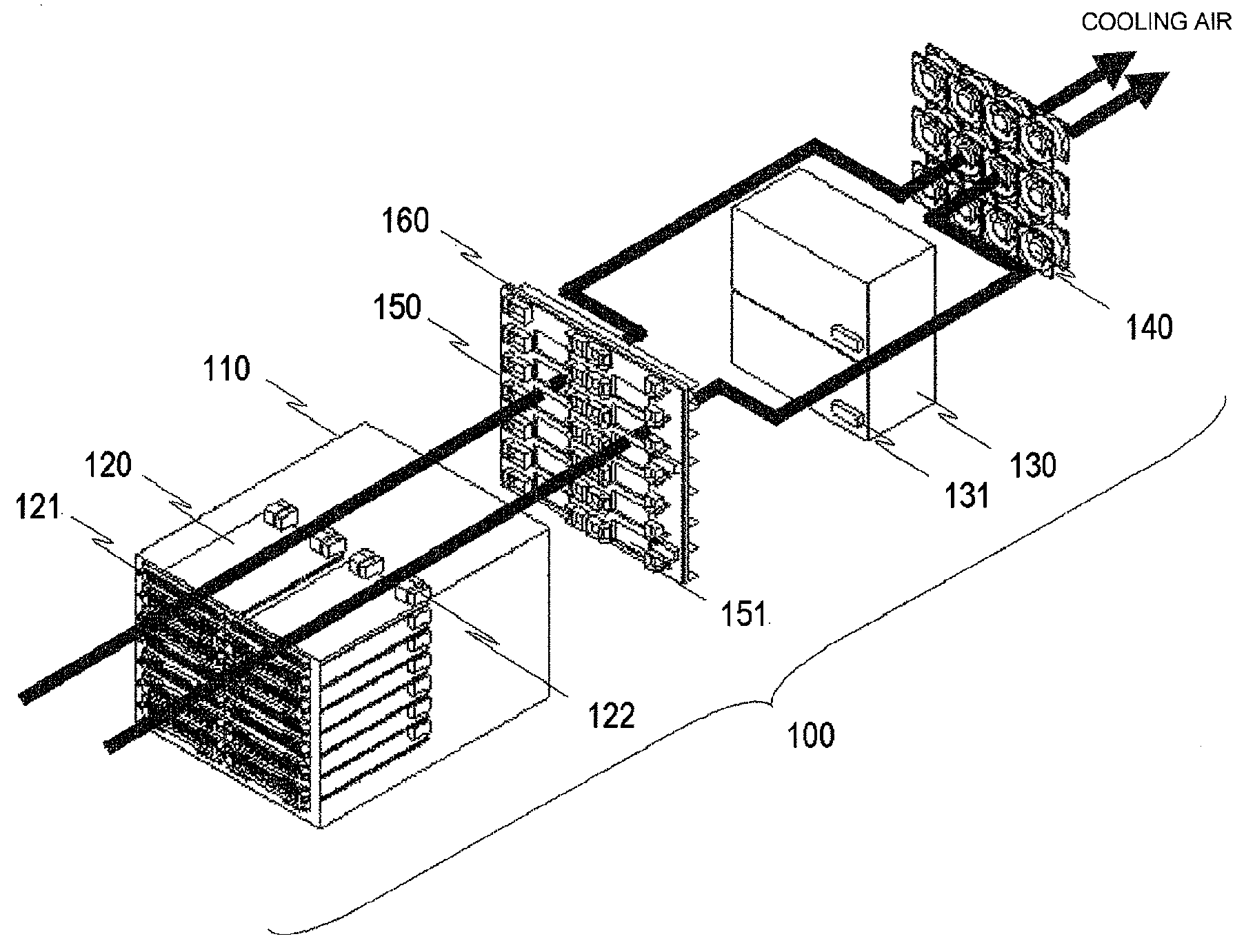
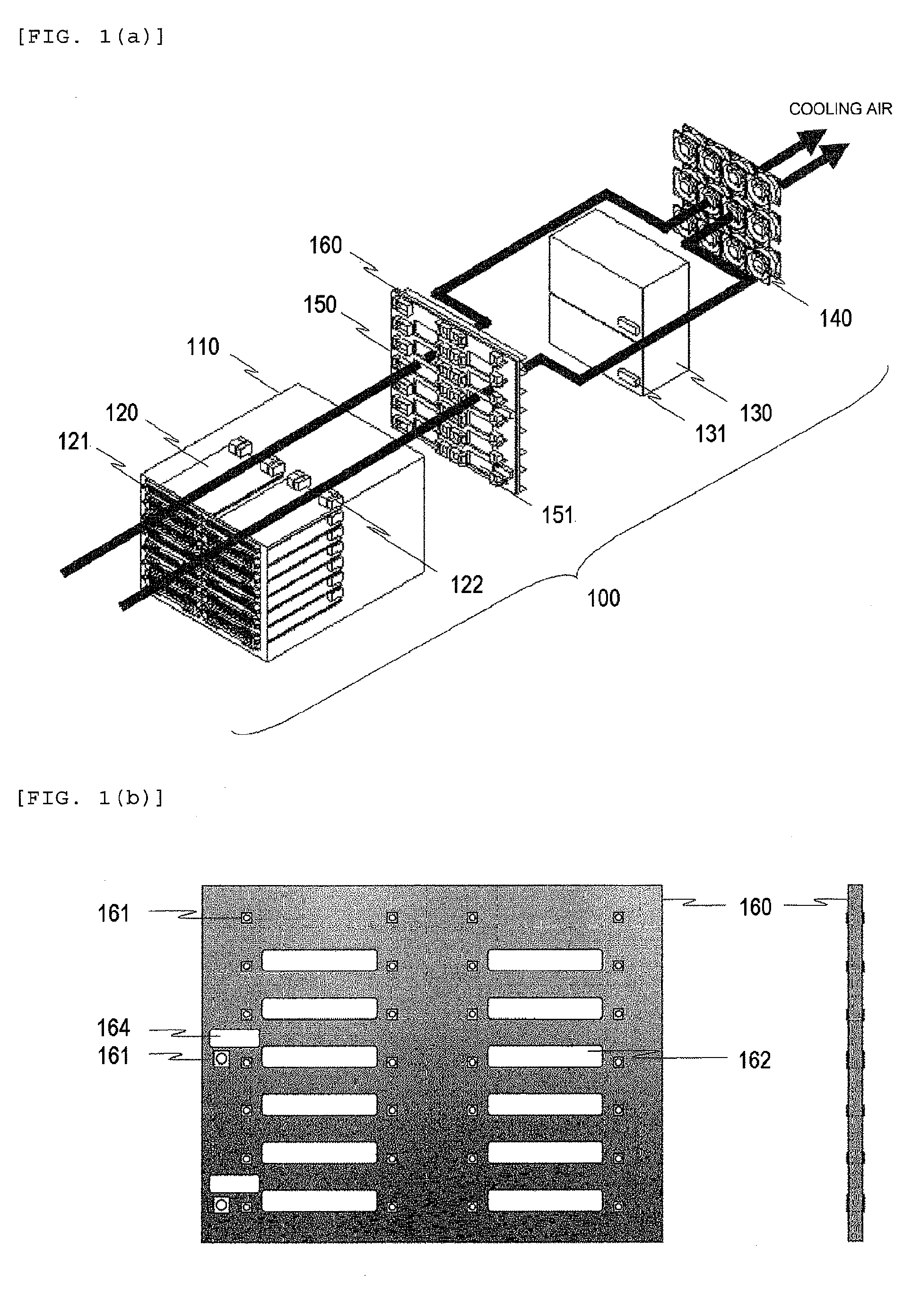
[0035]FIG. 1(a) illustrates a front side perspective view of the electronic device 100. The electronic device 100 includes a plurality of circuit board units 120, a plurality of front power units 130, a plurality of cooling units 140, a backplane 150, and a feed bus bar 160 within a housing 110.
[0036]The electronic device 100 of this embodiment has the plurality of circuit board units 120, and those units are implemented in a parallel state from a front surface of the device. The circuit board units 120 are each configured by a circuit board on which a semiconductor element is mounted, and realize a variety of functions for conducting packet transfer. For example, the circuit board units 120 include a circuit board unit that conducts an interface control with an external, a destination retrieval of a packet, and transfer processing of the packet, a circuit board unit that switches the packet to a desired port, and a circuit board unit that conducts a basic control of the electronic ...
second embodiment
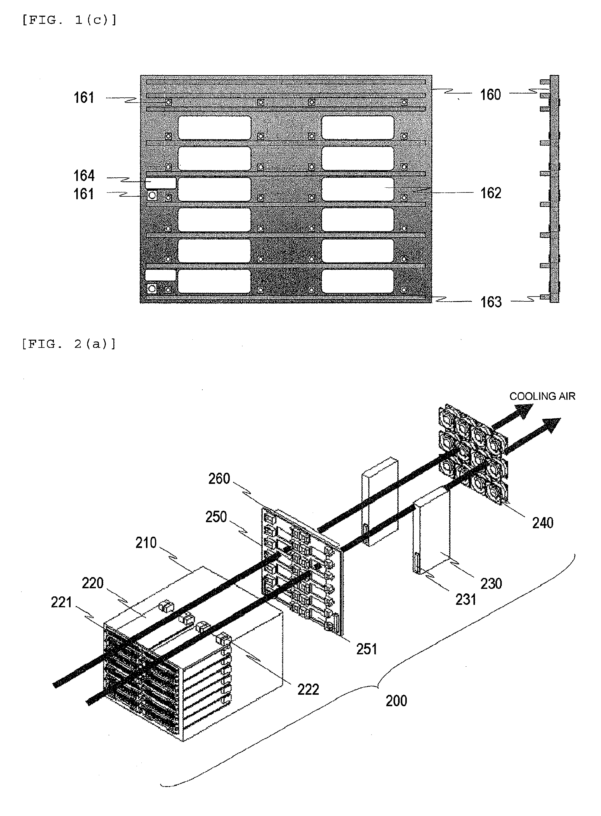
[0052]FIG. 2(a) illustrates a perspective view of a front surface side of the electronic device 200. The electronic device 200 includes a plurality of circuit board units 220, a plurality of front power units 230, a plurality of cooling units 240, a backplane 250, and a feed bus bar 260 within a housing 210.
[0053]The electronic device 200 of this embodiment is a modified example of the electronic device 100 in the first embodiment. A large difference of the electronic device 200 from the electronic device 100 of the first embodiment resides in a structure where the front power units 230 are implemented on right and left of a rear surface of the device in a vertical state to ensure a passage of the cooling air.
[0054]With this configuration, as compared with the electronic device 100 of the first embodiment, because a direction of the cooling air is linear, the cooling performance of the device can be improved. The other structures are identical with those in the electronic device 100...
third embodiment
[0058]FIG. 3(a) illustrates a perspective view of a front surface side of the electronic device 300. The electronic device 300 includes a plurality of circuit board units 320, a plurality of front power units 330, a plurality of cooling units 340, a backplane 350, and a feed bus bar 360 within a housing 310.
[0059]A large difference of the electronic device 300 from the electronic device 100 of the first embodiment and the electronic device 200 of the second embodiment resides in a structure where the circuit board units 320 are implemented in a horizontal state from a front surface of the device, and implemented in a vertical state in the center of a rear surface of the device.
[0060]The circuit board units 320 implemented on the rear surface of the device are, for example, circuit board units having a function of a cross bar switch. The cross bar switch is a circuit board unit having a function of switching a packet arrived from the circuit board units 320 implemented from the front...
PUM
 Abstract
Description
Claims
Application Information
 - R&D
- Intellectual Property
- Life Sciences
- Materials
- Tech Scout
- Unparalleled Data Quality
- Higher Quality Content
- 60% Fewer Hallucinations
Browse by: Latest US Patents, China's latest patents, Technical Efficacy Thesaurus, Application Domain, Technology Topic, Popular Technical Reports.
© 2025 PatSnap. All rights reserved.Legal|Privacy policy|Modern Slavery Act Transparency Statement|Sitemap|About US| Contact US: help@patsnap.com