Two speed direct drive drawworks

a drawwork and two-speed technology, applied in the direction of dynamo-electric converter control, magnetic circuit shape/form/construction, hoisting equipment, etc., to achieve the effect of increasing personnel safety and avoiding equipment damag

Active Publication Date: 2013-09-19
CANRIG DRILLING TECH
View PDF5 Cites 13 Cited by
  • Summary
  • Abstract
  • Description
  • Claims
  • Application Information

AI Technical Summary

Benefits of technology

[0041]The present invention implements a over-speed detector to open the power supply (i.e. the variable frequency drive system power circuit) and instantaneously insert dynamic braking resistors or a “load bank” so as to absorb the kinetic energy of the rotating drum of the winch or drawworks that is produced from the potential energy from a weight or a “load” (i.e. the drill string and associated traveling and drilling equipment suspended from the drawworks hook) in order to slow down this condition. This ensures a maximum safer speed limited relative to the associated load of the weight (known as “weight-on-bit” or the free suspended weight of the drill string and related drilling equipment). As such, the load is prevented from crashing when in a runaway condition.
[0043]During runaway conditions or overspeed occurrences, the stator power terminals are immediately disconnected through power switches and connected to a load bank or a resistor network to absorb the lowering power and limit the top speed or maximum speed of the falling load. Due to the inherent characteristics of the field flux being produced from the permanent magnet motor, this dynamic braking system utilizes the driving motor itself as the braking device. As such, the present invention can avoid equipment damage and increase personnel safety.

Problems solved by technology

This condition can be an interruption of power from the power supply to the permanent magnet or an overload condition affecting the drum.

Method used


Image

  • Two speed direct drive drawworks
  • Two speed direct drive drawworks
  • Two speed direct drive drawworks

Examples


Embodiment Construction

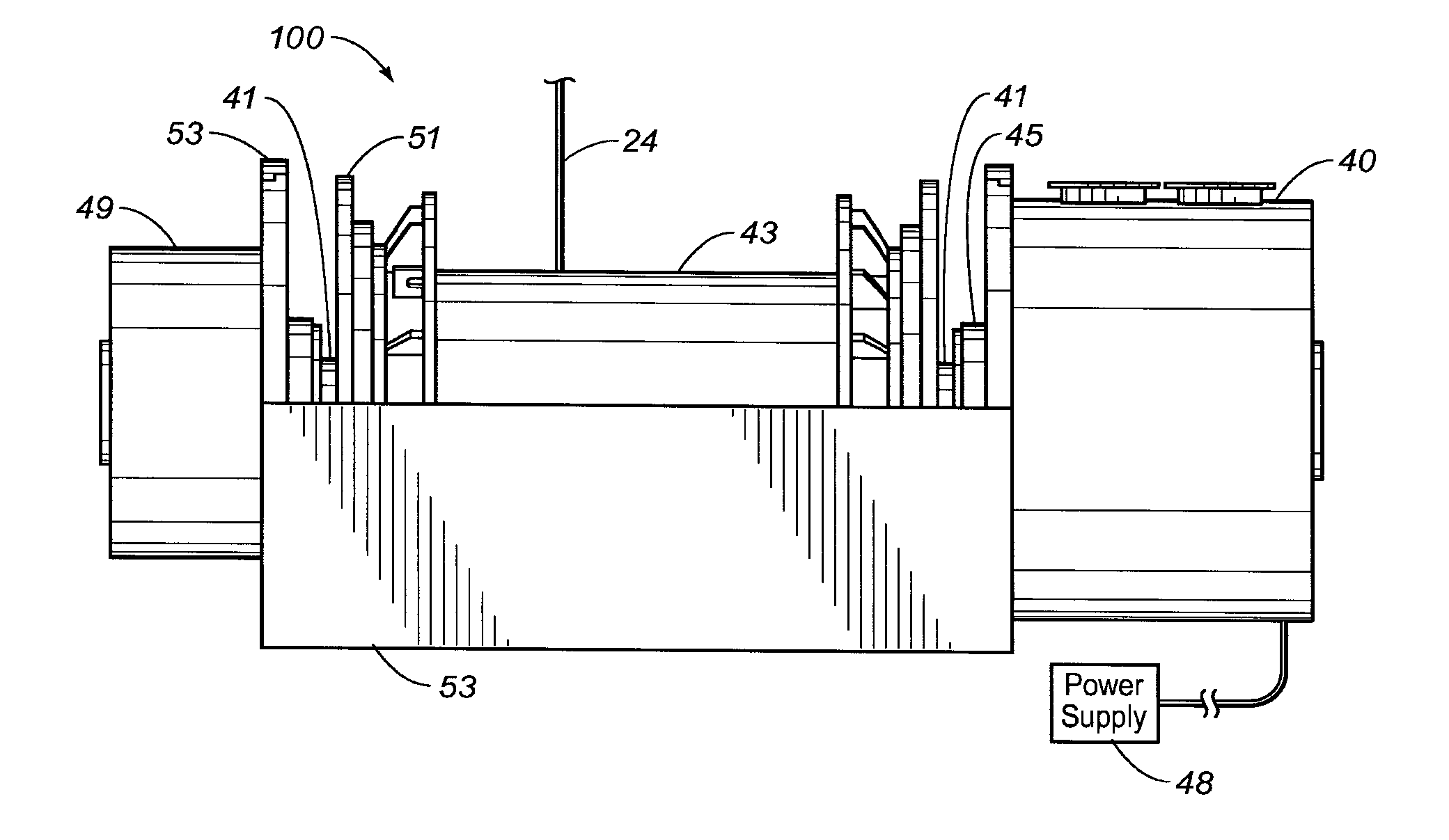
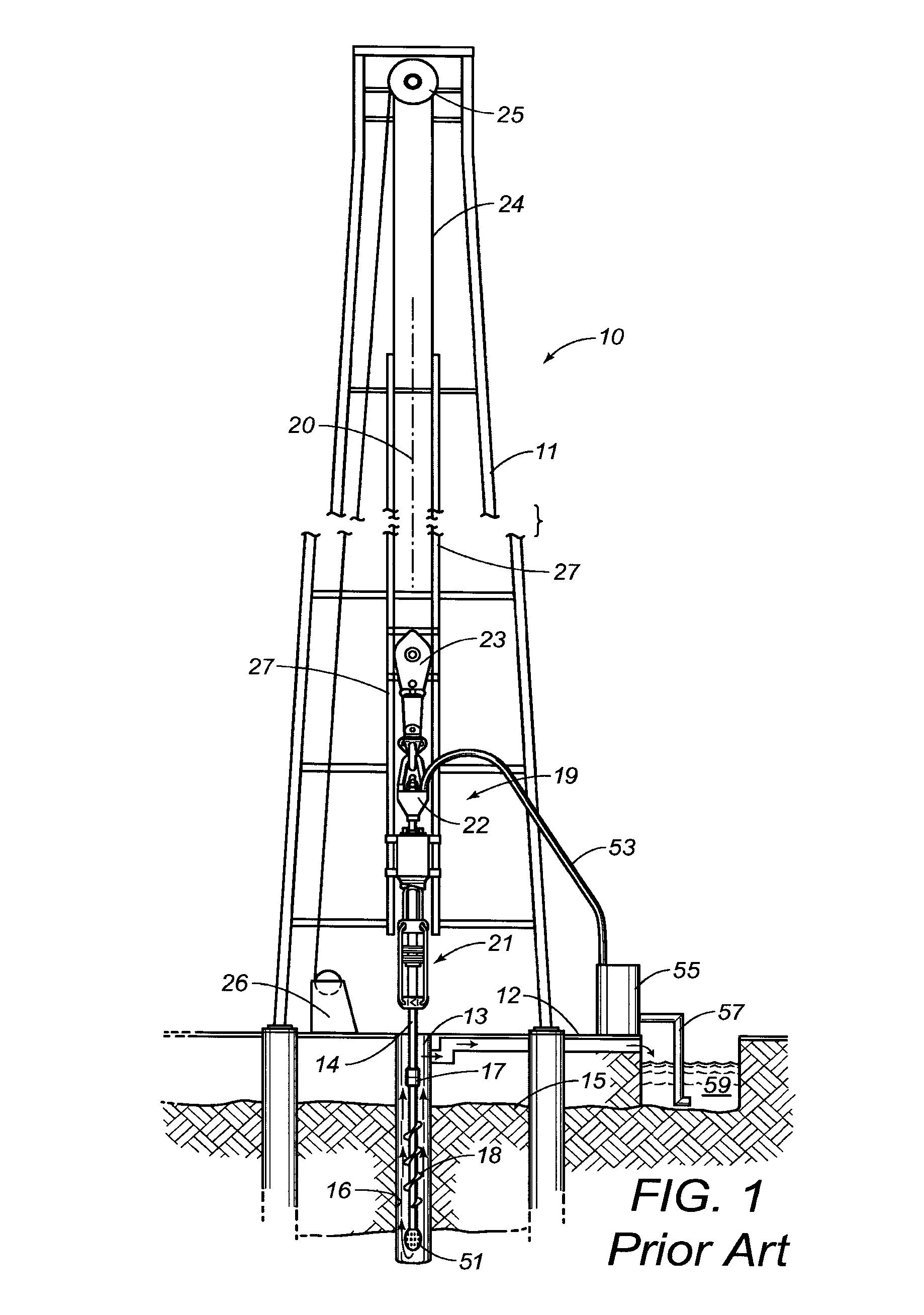
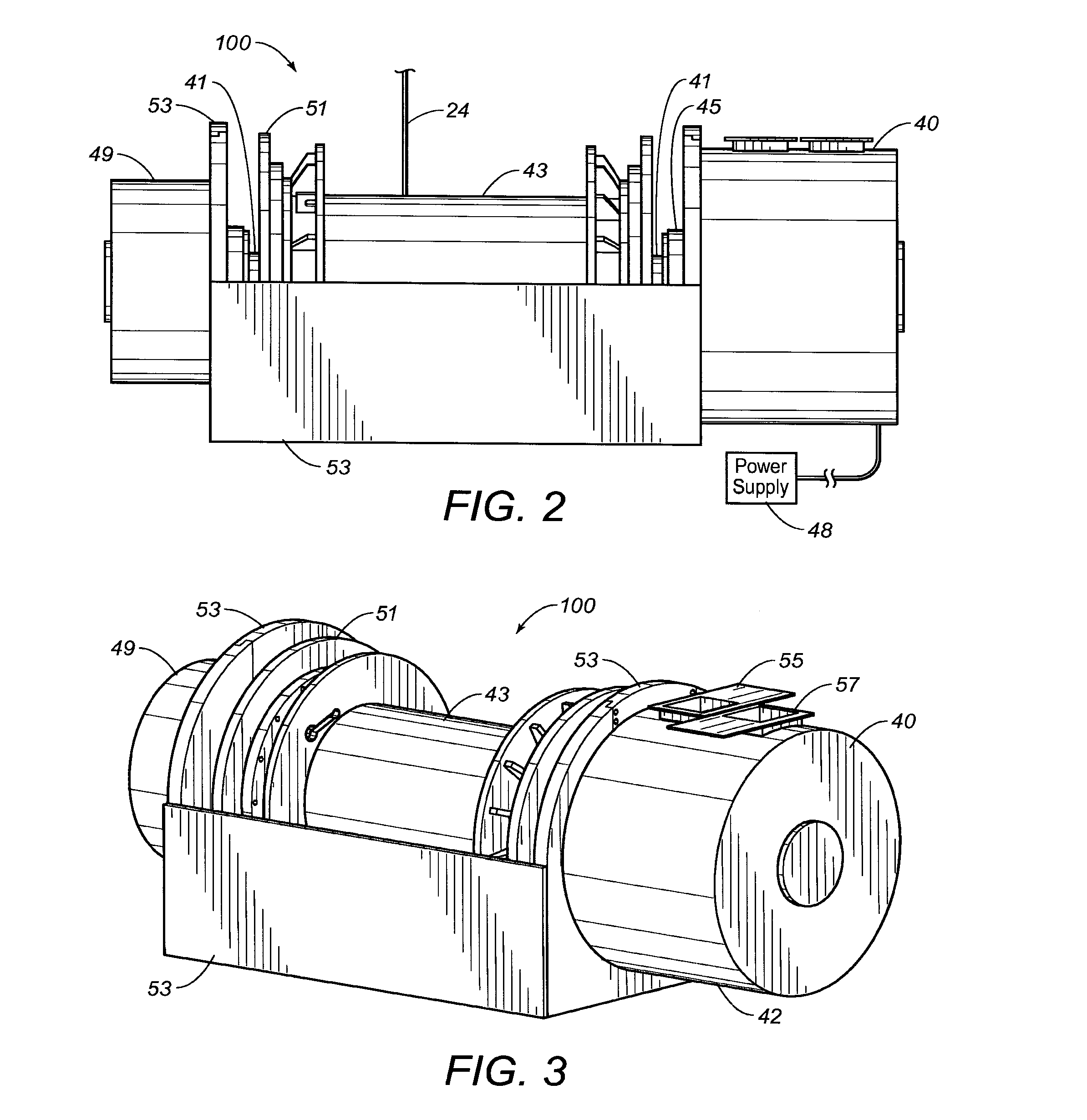
[0055]Referring to FIG. 2, there is shown a side elevational view of the preferred embodiment of the permanent magnet direct drive drawworks 100 of the present invention. The drawworks 100 has a permanent magnet motor 40. A shaft 41 is connected to the permanent magnet motor 40. A bearing housing 45 is positioned adjacent the permanent magnet motor 40 and the shaft 41. The shaft 41 extends through the bearing housing 45 and into the interior of the motor 40. A drum 43 is attached to the end 47 of the shaft 41 opposite the permanent magnet motor 40. The wire line 24 wraps around the drum 43. The drum 43 is in cradle 53. The cradle 53 supports the shaft 41 so as to hold the drum 43 and motor 40 above the floor surface, e.g. the rig floor 12. A braking system 49 is positioned on a side of the drum 43 opposite the motor 40. In FIG. 2, the braking system 49 has a brake disk 51 positioned adjacent the drum 43. The braking system 49 in FIG. 2 is water-cooled. A power supply 48 is connected...


PUM


Abstract

A direct drive drawworks (100) has a permanent magnet motor (40) with a first set of windings (250) and a second set of windings (252), a shaft (41) extending from the permanent magnet motor (40) such that the permanent magnet motor directly rotates the shaft (41), a drum (43) connected to the shaft (41) away from the permanent magnet motor (40) such that the rotation of the shaft (41) causes a corresponding rotation of the drum (43), and a switch cooperative with the first set of windings and the second set of windings so as to cause the sets of windings to be selectively connected in parallel or in series.

Description

FIELD OF THE INVENTION[0001]The present invention relates to oil field equipment. More particularly, the present invention the relates to a drawworks used in oil and gas drilling and production. More particularly, the present invention relates to a drawworks having a permanent magnet motor. Additionally, the present invention relates to permanent magnet motor drive systems that are capable of selectively operating at two different speeds.BACKGROUND OF THE INVENTION[0002]A drawworks is a common piece of oil field equipment that is used in oil and gas drilling and production. A drawworks is typically mounted near an oil rig. A common function of a drawworks is to raise and lower drill pipe and casing out of and into a wellbore. A drawworks can be referred to as a hoist or a winch. There are many different sizes of drawworks that are used in the drilling and mining industries. The sizes of the drawworks are reflected in the power ratings for such drawworks. These drawworks share simila...

Claims


Application Information

Patent Timeline
Patent Type & Authority Applications(United States)
IPC IPC(8): B66D1/12E21B19/00H02P3/12H02P7/06G05B11/01
CPCB66D1/12E21B19/008H02K3/28H02P3/22H02P7/06H02K21/14H02K1/32G05B11/01H02P3/12H02P25/188
Inventor WILLIAMS, KEVIN R.
Owner CANRIG DRILLING TECH
Why Eureka
Try Eureka