Reference voltage generating circuit and reference voltage source

Active Publication Date: 2013-09-19
PANASONIC SEMICON SOLUTIONS CO LTD
View PDF8 Cites 11 Cited by
  • Summary
  • Abstract
  • Description
  • Claims
  • Application Information

AI Technical Summary

Benefits of technology

[0019]A reference voltage source according to another aspect of the present invention includes: the reference voltage generating circuit configured as above; and an amplifier configured to amplify the reference voltage. Since to the reference voltage source configured as above outputs the reference voltage in which the first-order temperature coefficient a

Problems solved by technology

However, in a case where a plurality of correction current generating circuits are provided as in PTL 1, the problem is that the circuit configuration becomes complex.
In addition, in a case where the differen

Method used


Image

  • Reference voltage generating circuit and reference voltage source
  • Reference voltage generating circuit and reference voltage source
  • Reference voltage generating circuit and reference voltage source

Examples


embodiment 1

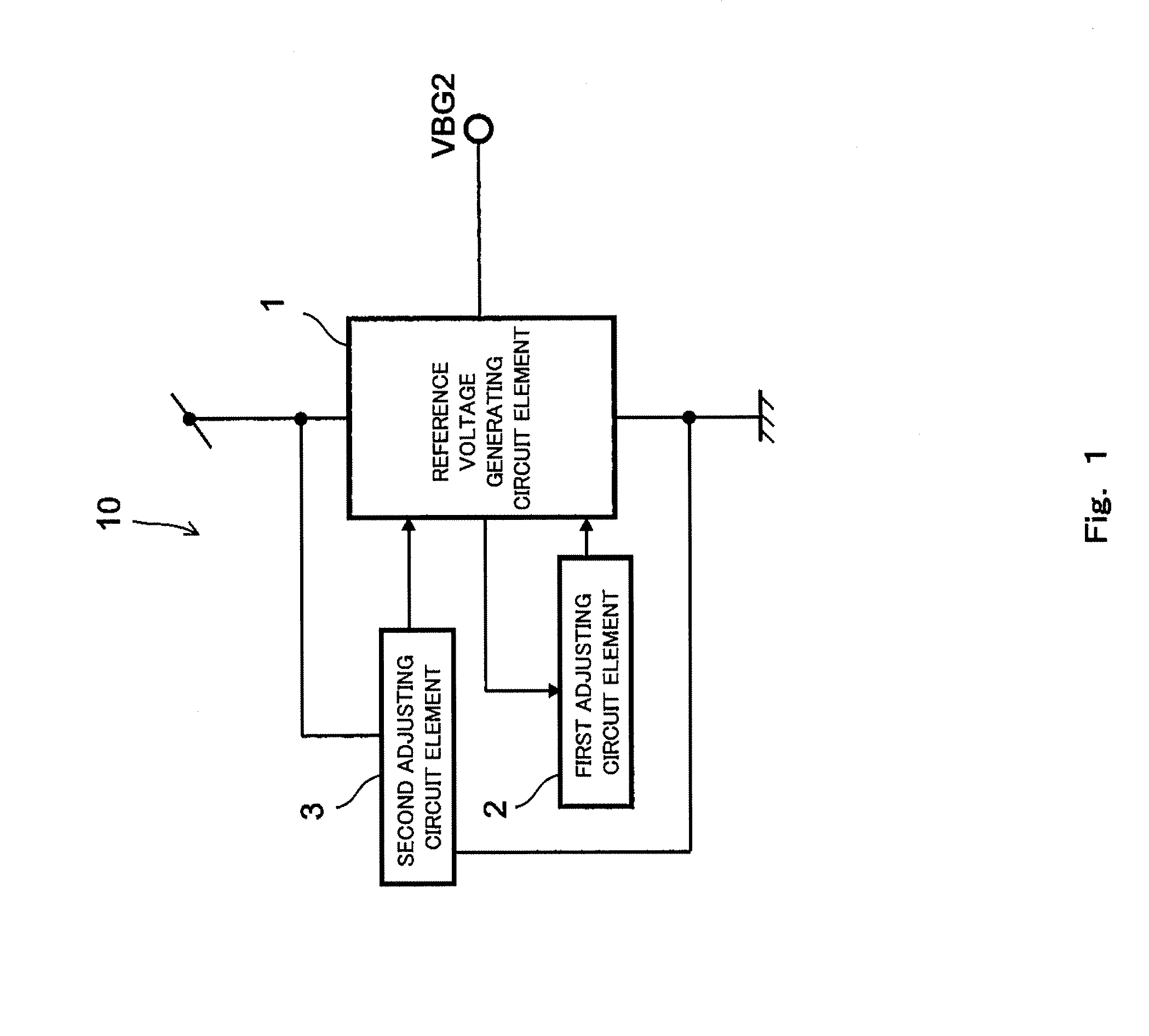
[0038]First, a reference voltage generating circuit according to Embodiment 1 of the present invention will be explained. FIG. 1 is a circuit diagram showing a schematic configuration example of the reference voltage generating circuit according to Embodiment 1 of the present invention.

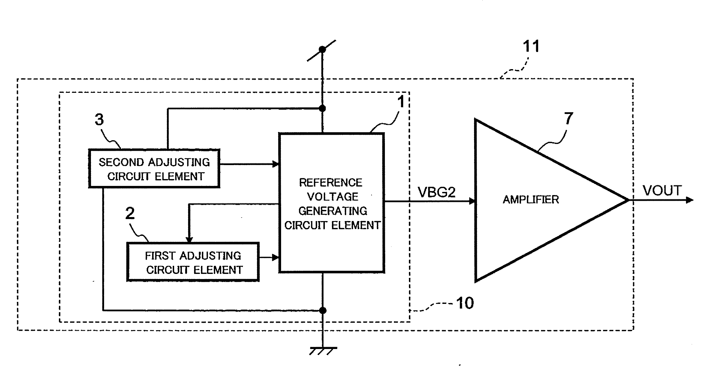
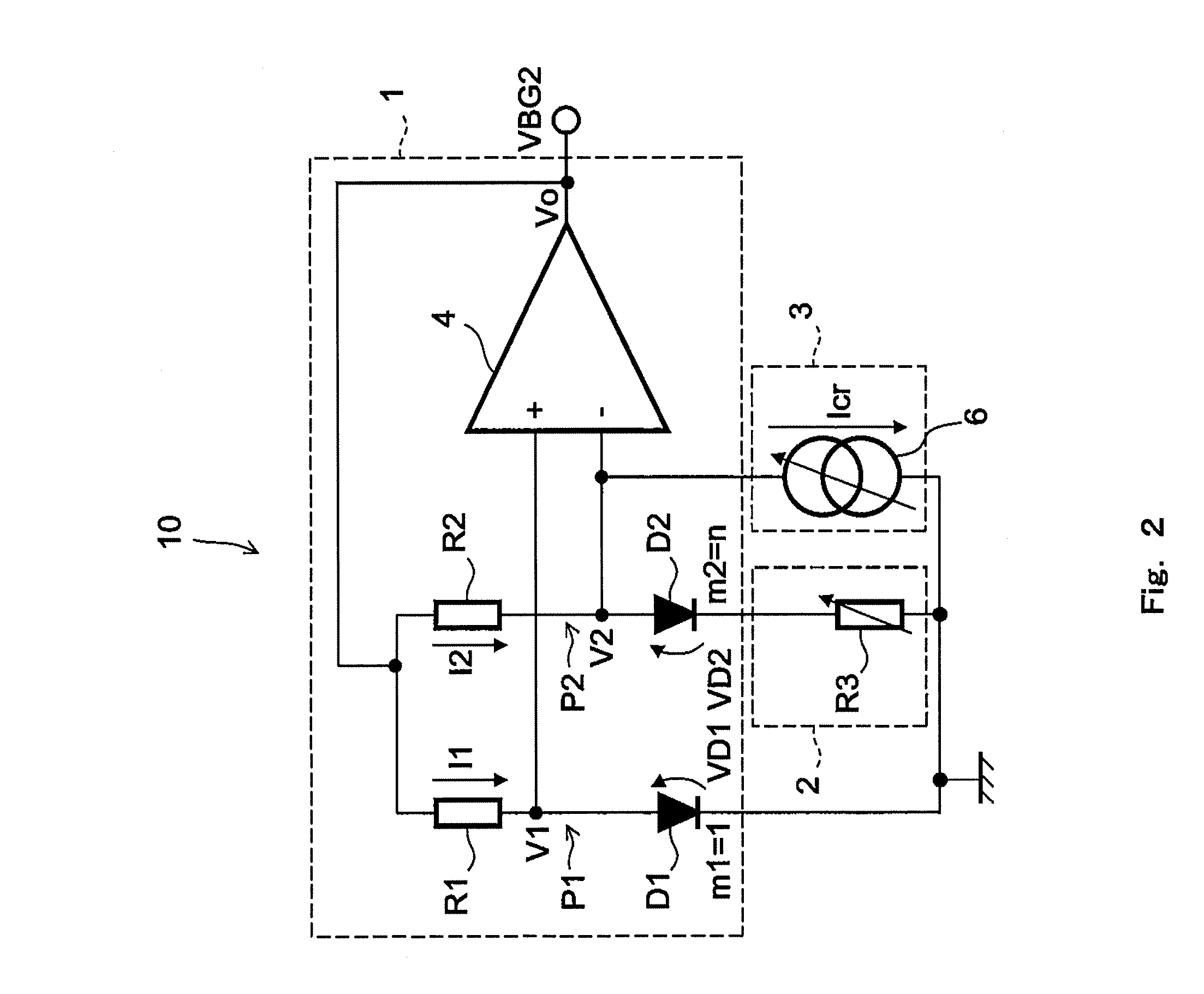
[0039]As shown in FIG. 1, a reference voltage generating circuit 10 according to the present embodiment includes a reference voltage generating circuit element 1, a first adjusting circuit element 2, and a second adjusting circuit element 3. The reference voltage generating circuit element 1 includes a first diode characteristic element (described later) and a second diode characteristic element (described later) and outputs a reference voltage VBG1 generated based on the difference between voltages respectively applied to the first diode characteristic element and the second diode characteristic element. The density of a current flowing through the second diode characteristic element is different fro...

embodiment 2

[0063]Next, the reference voltage generating circuit according to Embodiment 2 of the present invention will be explained. FIG. 3 is a circuit diagram showing a schematic configuration example of the reference voltage generating circuit according to Embodiment 2 of the present invention. In the present embodiment, the same reference signs are used for the same components as in Embodiment 1, and a repetition of the same explanation is avoided. A reference voltage generating circuit 10B of the present embodiment is different from the reference voltage generating circuit 10 of Embodiment 1 in that a reference voltage generating circuit element 1B includes a first current source element S1 and a second current source element S2. The first current source element S1 adjusts based on the output of the differential amplifier 4 a current flowing through the first path P1, and the second current source element S2 adjusts based on the output of the differential amplifier 4 a current flowing th...

modification example of embodiment 2

[0084]Next, Modification Example of the reference voltage generating circuit according to Embodiment 2 of the present invention will be explained. FIG. 11 is a circuit diagram showing a schematic configuration example of the reference voltage generating circuit according to Modification Example of Embodiment 2 of the present invention. In the present modification example, the same reference signs are used for the same components as in Embodiment 2, and a repetition of the same explanation is avoided. A reference voltage generating circuit 10C of the present modification example is different from the reference voltage generating circuit of Embodiment 2 in that a second adjusting circuit element 3C generates the adjust current Icr between the second resistor R2 and the second diode characteristic element D2. Specifically, in the second adjusting circuit element 3C, the output terminal of the current mirror circuit element 5 is connected to a portion between the second resistor R2 and ...


PUM


Abstract

The present invention provides a reference voltage generating circuit capable of improving a temperature dependence characteristic by a simple configuration. The reference voltage generating circuit includes: a reference voltage generating circuit element including a first diode characteristic element and a second diode characteristic element, a density of a current flowing through the second diode characteristic element being different from a density of a current flowing through the first diode characteristic element, the reference voltage generating circuit element being configured to output a reference voltage generated based on a difference between voltages respectively applied to the first diode characteristic element and the second diode characteristic element; a first adjusting circuit element configured to adjust a first-order temperature coefficient of the reference voltage; and a second adjusting circuit element configured to adjust a second-order temperature coefficient of the reference voltage.

Description

[0001]This is a continuation application under 35 U.S.C 111(a) of pending prior International application No. PCT / JP2012 / 001636, filed on Mar. 9, 2012.BACKGROUND OF THE INVENTION[0002]1. Field of the Invention[0003]The present invention relates to a reference voltage generating circuit configured to generate a predetermined reference voltage and a reference voltage source including the reference voltage generating circuit, particularly to a reference voltage generating circuit and a reference voltage source each having an excellent temperature characteristic.[0004]2. Description of the Related Art[0005]Reference voltage generating circuits configured to stably supply a predetermined reference voltage at any temperature have been known. FIG. 14 is a circuit diagram showing a basic configuration of a conventional reference voltage generating circuit. As shown in FIG. 14, a reference voltage generating circuit 110 includes a first path P10, a second path P20, and a differential amplifi...

Claims


Application Information

Patent Timeline
IPC IPC(8): G05F3/22
CPCG05F3/222G05F3/30
Inventor OZASA, MASAYUKIINUKAI, FUMIHITO
Owner PANASONIC SEMICON SOLUTIONS CO LTD
Why Eureka
Try Eureka