Rotation angle detector

a detector and rotation angle technology, applied in the field of rotation angle detectors, can solve the problems of difficult to make the rotation angle detector compact in size, and achieve the effect of compact size and stable detection accuracy

Inactive Publication Date: 2013-09-19
HITACHI ASTEMO LTD
View PDF19 Cites 13 Cited by
  • Summary
  • Abstract
  • Description
  • Claims
  • Application Information

AI Technical Summary

Benefits of technology

[0007]The present invention has been made with the foregoing situation taken into consideration. An object of the present invention is to provide a rotation angle detector which is compact in size and has a stable accuracy for detecting the rotation angle, by making the curvature of magnetic flux near an end surface of a magnet small and placing a magneto-electric transducer in that location.

Problems solved by technology

In this case, however, it is difficult to make the rotation angle detector compact in size.

Method used


Image

  • Rotation angle detector
  • Rotation angle detector
  • Rotation angle detector

Examples


Embodiment Construction

[0018]Descriptions will be provided hereinbelow of an embodiment of the present invention on the basis of the accompanying drawings.

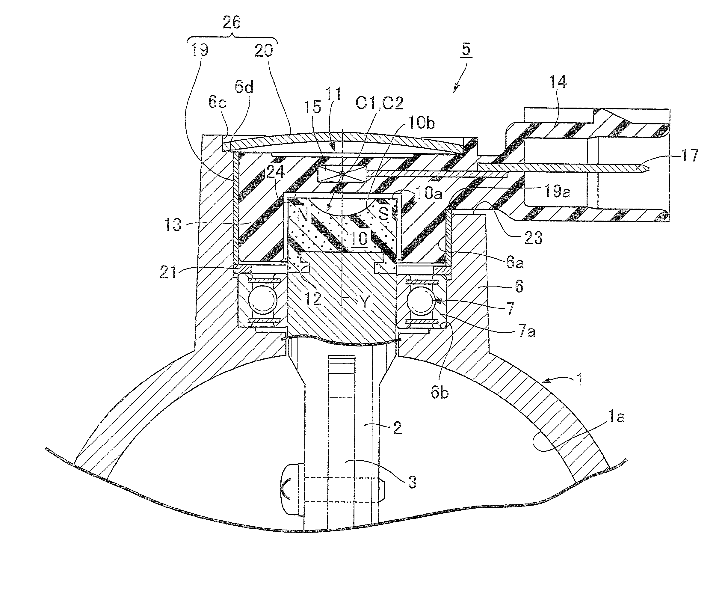
[0019]First of all, in FIG. 1, reference numeral 1 denotes a throttle body constituting a part of an intake system of an engine. The throttle body 1 includes, in its inside, an intake passage 1a communicating with an intake port of the engine. A rotating shaft 2 placed traversing the intake passage 1a is rotatably supported by the throttle body 1. A butterfly-type throttle valve 3 configured to open and close the intake passage 1a is screwed to the rotating shaft 2. A throttle lever for manual operation or an electric motor for automatic operation therefor (neither of which is shown) is connected to an end portion of the rotating shaft 2. A rotation angle detector 5 configured to detect the opening degree of the throttle valve 3 is connected to the opposite end portion of the rotating shaft 2.

[0020]A pair of cylindrical bearing bosses 6 (only one of whi...


PUM


Abstract

A rotation angle detector includes: a magnet attached to a rotating shaft and magnetized in a certain direction orthogonal to an axis of the rotating shaft; and a non-rotary magneto-electric transducer placed to be opposed to an end surface of the magnet, and configured to detect a rotation angle of the rotating shaft in cooperation with the magnet through magneto-electric transduction. A concave curved surface is formed in the end surface of the magnet in order to make a magnetic flux of a magnetic field facing the end surface of the magnet closer to the magnet and flattened. Accordingly, it is possible to provide a rotation angle detector which is compact in size and has a stable accuracy for detecting the rotation angle, by making the curvature of the magnetic flux near the end surface of the magnet small and placing the magneto-electric transducer in that location.

Description

CROSS-REFERENCE TO RELATED APPLICATION[0001]The present application claims priority under 35 USC 119 to Japanese Patent Application No. 2012-57143 filed on Mar. 14, 2012 the entire contents of which are hereby incorporated by reference.BACKGROUND OF THE INVENTION[0002]1. Field of the Invention[0003]The present invention relates to an improvement of a rotation angle detector comprising: a magnet attached to a rotating shaft, and magnetized in a certain direction orthogonal to an axis of the rotating shaft; and a non-rotary magneto-electric transducer placed so as to be opposed to an end surface of the magnet, and configured to detect a rotation angle of the rotating shaft in cooperation with the magnet through magneto-electric transduction.[0004]2. Description of the Related Art[0005]Such a rotation angle detector is already known, as disclosed in, for example, Japanese Patent Application Laid-open No. 2009-19926.[0006]As shown in FIG. 3, in a solid cylindrical magnet 010 of such a c...

Claims


Application Information

Patent Timeline
Patent Type & Authority Applications(United States)
IPC IPC(8): G01B7/30
CPCG01D5/145G01B7/30G01D2205/40G01D2205/77
Inventor AKABANE, AKIRA
Owner HITACHI ASTEMO LTD
Why Eureka
Try Eureka