LED Light Fixture With Improved Thermal Management

a technology of led light fixtures and thermal management, which is applied in the direction of semiconductor devices for light sources, lighting and heating apparatus, planar light sources, etc., can solve the problems of heavy weight and additional costs of conventional light systems manufactured with sheet metal, metal heat sinks can add significant cost and weight to a light fixture, and tools/molds cannot be easily modified and maintained

Inactive Publication Date: 2013-09-19
GRAFTECH INT HLDG INC
View PDF18 Cites 80 Cited by
  • Summary
  • Abstract
  • Description
  • Claims
  • Application Information

AI Technical Summary

Benefits of technology

[0009]The light fixture of the disclosure also includes a heat spreader positioned in thermal contact with both the circuit board and the enclosure, the heat spreader having a surface area at least twice that of the circuit board and a thermo-mechanical design constant of at least 10 mm-W / m*K, more preferably at least about 75 mm-W / m*K; in the most advantageous embodiments, the heat spreader has a thermo-mechanical design constant of at least about 100 mm-W / m*K. In many embodiments, the heat spreader has an in-plane thermal conductivity of at least about 140 W / m*K, more preferably at least about 220 W / m*K (all thermal conductivity measurements provided herein are taken at room temperature, 20° C.). The heat spreader should be at least about 0.075 mm in thickness, up to about 10 mm in thickness. Most commonly, the heat spreader is from about 0.1 mm to about 3 mm in thickness. In some embodiments, the heat spreader is formed of a material selected from the group consisting of copper, aluminum, compressed particles of exfoliated graphite and pyrolytic graphite. In one specific embodiment, the heat spreader is formed of at least one sheet of compressed particles of exfoliated graphite, and, in additional embodiments, the heat spreader extends at least partially across the opening of the enclosure and / or is in thermal contact with the major surface of the enclosure defining the surface of the cavity, such as by the use of an adhesive, rivets, screws or combinations thereof.

Problems solved by technology

To handle this internal conduction path to a suitable area for convection, most LED array lights have been developed using a metallic, especially an aluminum, heat sink, which causes a weight problem and additional costs over conventional light systems which are manufactured with sheet metal.
More particularly, such metallic heat sinks can add significant cost and weight to a light fixture, especially since production of the casting or extrusion tool, or the injection mold, used to form the heat sink is so difficult and time consuming, and the tools / molds do not last long and cannot be easily modified, especially as compared with sheet metal dies.
Conventional sheet metal designs are deficient in providing an adequate thermal path for the LED thermal dissipation.

Method used


Image

  • LED Light Fixture With Improved Thermal Management
  • LED Light Fixture With Improved Thermal Management
  • LED Light Fixture With Improved Thermal Management

Examples


Embodiment Construction

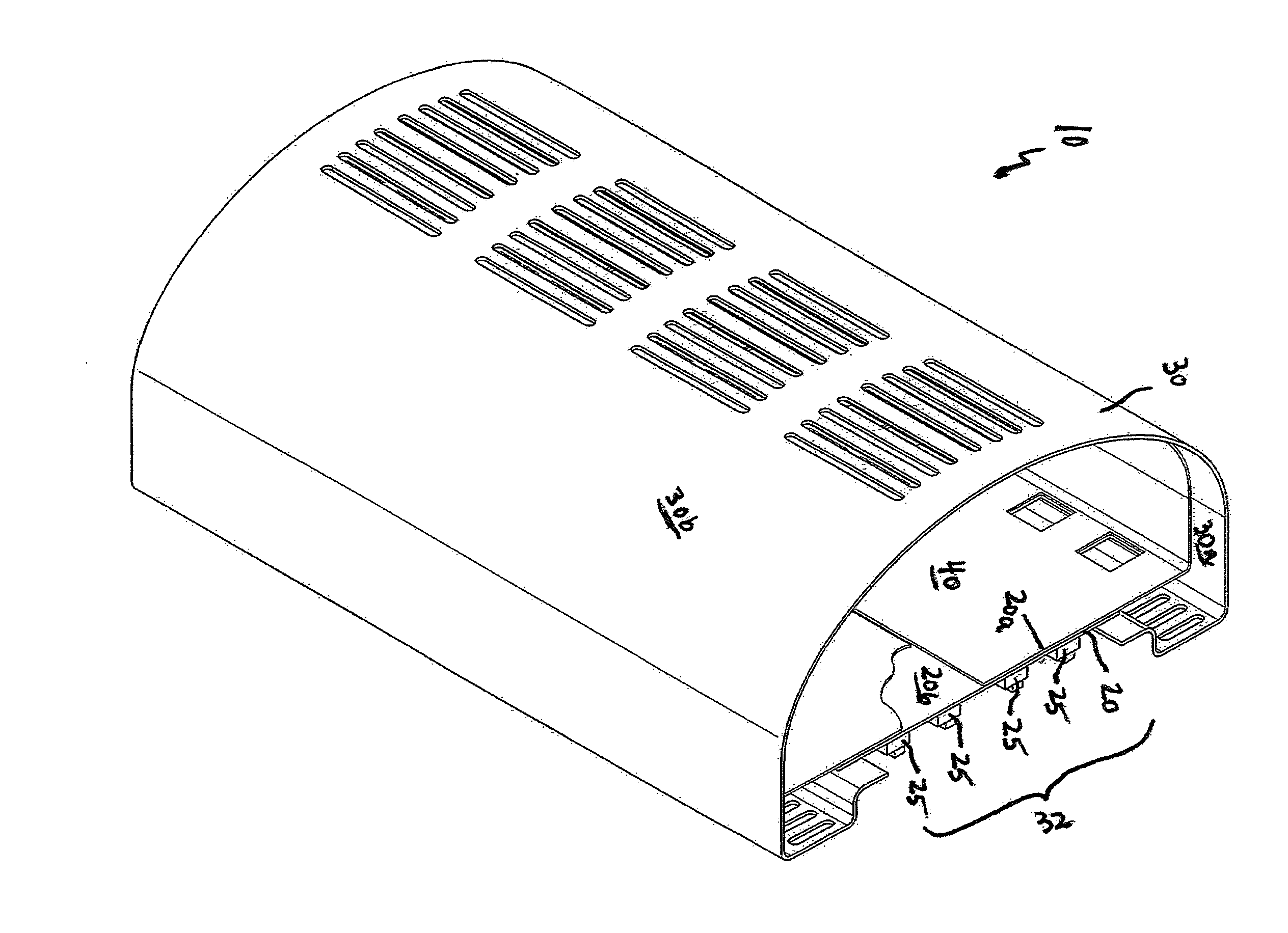
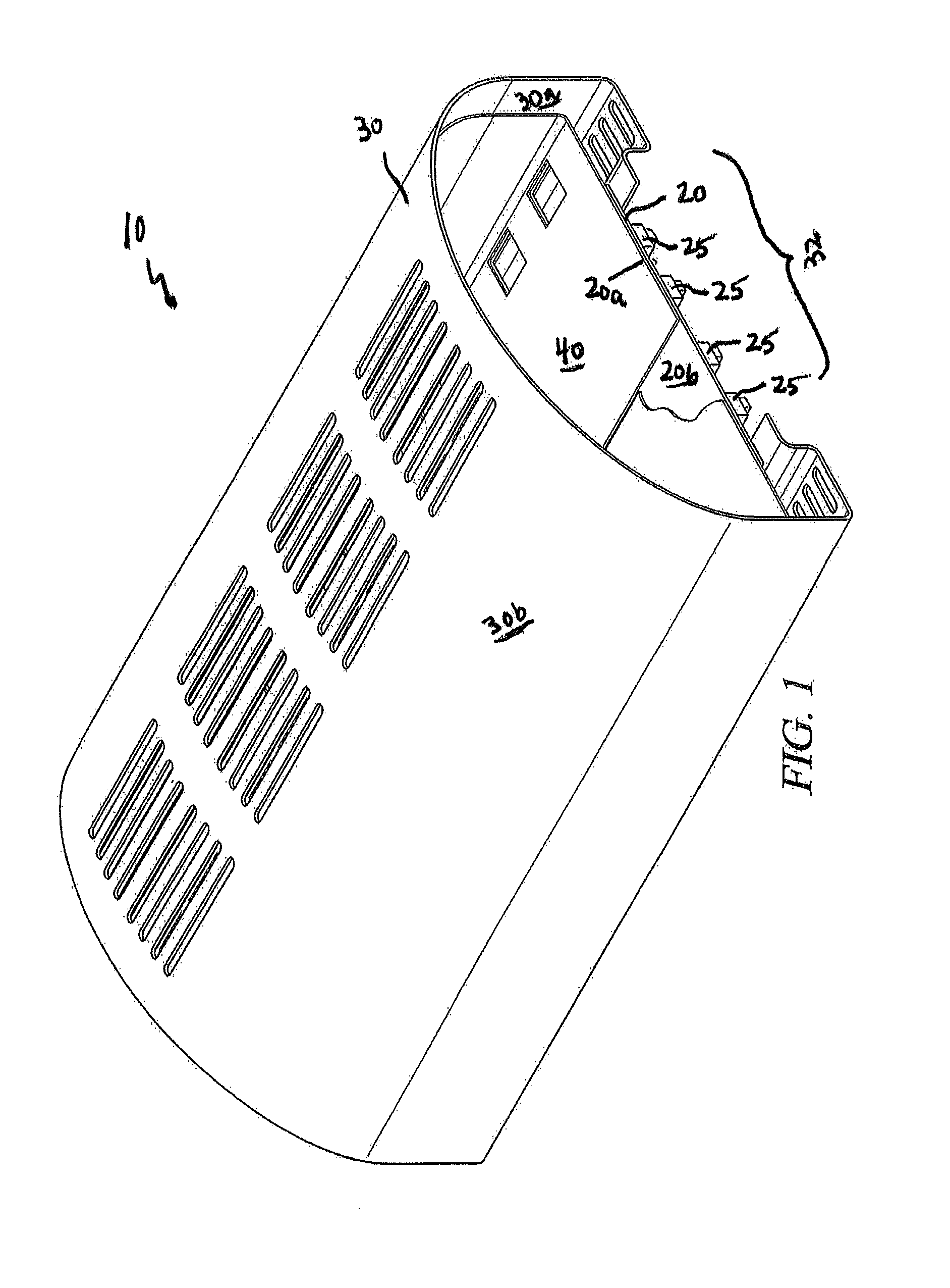
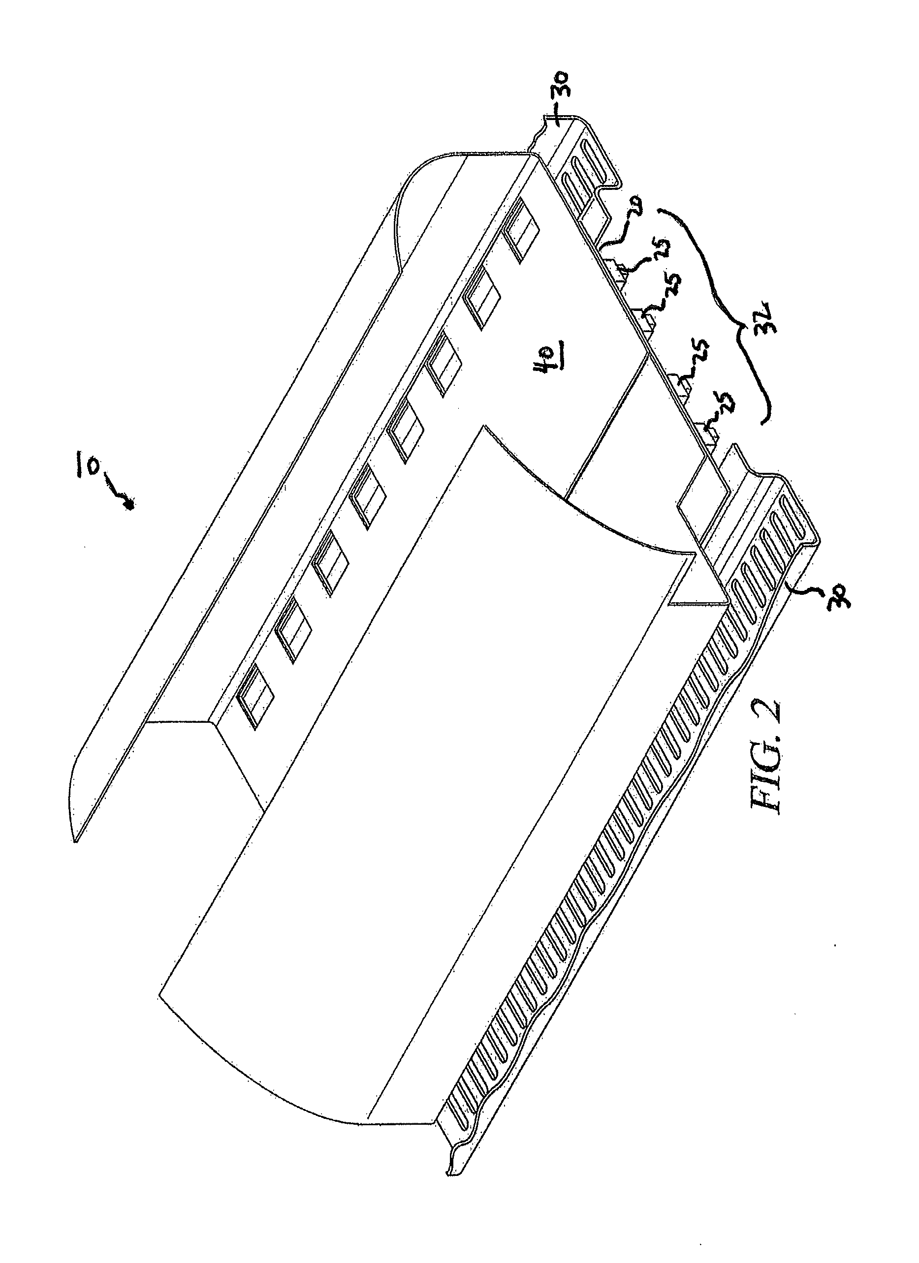
[0016]As noted, the present disclosure relates to light fixtures incorporating light-emitting diodes, or LEDs. By “light fixture” is meant a device intended for use in providing illumination for an area, either singly or in combination. An LED light fixture uses LEDs as the source of illumination. As is typical, one or more LEDs are mounted on a circuit board which controls the illumination of the LED. One or more such circuit boards can be employed in a light fixture. Of course, it will be readily recognized that it is necessary to enclose the circuit boards of an LED light fixture, both for safety reasons and to prevent damage to the circuit board caused by dust, dirt, or other environmental materials. Indeed, when an LED light fixture is mounted outdoors, such as in use as a streetlight or the like, protection from the elements is even more important. That said, it is also necessary to provide a way of dissipating the heat generated by the LED, to avoid temperature-caused degrada...


PUM


Abstract

A light fixture (10), having a circuit board (20) having first and second major surfaces (20a and 20b); at least one light emitting diode (25) mounted on the first major surface (20a) of the circuit board (20); an enclosure (30) formed of a material having two major surfaces (30a and 30b) and a thermo-mechanical design constant of at least 20 mm-W/m*K and shaped so as to define an opening (32) and a cavity (33), one of the major surfaces (30a) of the material defining the surface of the cavity (33) and the enclosure (30) positioned so as to enclose the second major surface (20b) of the circuit board (20); a heat spreader (40) having a surface area at least twice that of the circuit board and a thermo-mechanical design constant of at least 10 mm-W/m*K, the heat spreader (40) positioned in thermal contact with both the circuit board (20) and the enclosure (30).

Description

TECHNICAL FIELD[0001]The present disclosure relates to a light emitting diode (LED) light fixture, having improved thermal management. More specifically, the present disclosure relates to a light fixture which includes a circuit board having an LED mounted thereon, and an enclosure protecting the circuit board from, e.g., the elements. The enclosure includes a heat spreader which is in thermal contact with both the enclosure and the circuit board, to improve thermal management of the light fixture.BACKGROUND ART[0002]LEDs have become more efficient and cost effective for white lighting since the introduction of high brightness blue wavelengths. As the LED costs have dropped, the efficacies raised, and the amount of light per device increased steadily, new applications for LEDs have come into use. Recent levels of LED performance are now enabling applications across many fields, from specialty lighting (jewelry cases, refrigeration / freezer units, surgical lighting) to indoor general ...

Claims


Application Information

Patent Timeline
Patent Type & Authority Applications(United States)
IPC IPC(8): F21V29/00
CPCF21V15/01F21V29/004F21Y2101/02F21V29/763F21V29/002F21V29/507F21V29/75F21Y2105/001F21V29/70F21V29/85F21V29/89F21Y2105/10F21Y2115/10
Inventor PETRSOKI, JAMES T.REIS, BRADLEY E.NORLEY, JULIANSCHOBER, JOHNREYNOLDS, III, ROBERT A.XIONG, YIN
Owner GRAFTECH INT HLDG INC
Why Eureka
Try Eureka