Polymer batteries having thermal exchange apparatus

a polymer battery and thermal exchange technology, applied in the field of polymer batteries, can solve the problems of thermal runaway condition, irreversible damage to the electrochemical cells, insufficient heat dissipation from internal portions of the polymer electrochemical cell battery, and additional challenges to the thermal exchange mechanism, so as to achieve the effect of dissipating thermal energy

Inactive Publication Date: 2005-02-03
BATHIUM CANADA
View PDF13 Cites 130 Cited by
  • Summary
  • Abstract
  • Description
  • Claims
  • Application Information

AI Technical Summary

Benefits of technology

[0007] It is therefore an object of the present invention to provide a thermal exchange apparatus incorporated within a polymer battery casing that provides an efficient thermal path to dissipate the thermal energy generated by the electrochemical cells of a polymer battery regardless of the particular position of each electrochemical cell within the casing of the polymer battery.
[0013] The heat sink material may include a low friction film positioned between the resilient heat sink material and the inner surface of the walls of the thermally conductive structural housing. This film is adapted to ease relative movement between the resilient heat sink material and the walls of the structural housing.
[0018] a low friction film positioned between the resilient heat sink pads and the inner surface of the at least one of the walls, the film adapted to ease relative movement between the resilient heat sink pads and the at least one of the walls; and

Problems solved by technology

Such advanced battery systems typically produce a significant amount of heat which, if not properly dissipated, can result in a thermal runaway condition and irreversible damages to the electrochemical cells.
The conventional approach of providing an external heat transfer mechanism for example, is inadequate to effectively dissipate heat from internal portions of the polymer electrochemical cell battery.
Other characteristics of polymer battery technologies provide additional challenges for the thermal exchange mechanism.
Such repetitive changes in the physical size of a cell significantly complicate the mechanical design and the thermal management strategy.

Method used


Image

  • Polymer batteries having thermal exchange apparatus
  • Polymer batteries having thermal exchange apparatus
  • Polymer batteries having thermal exchange apparatus

Examples


Embodiment Construction

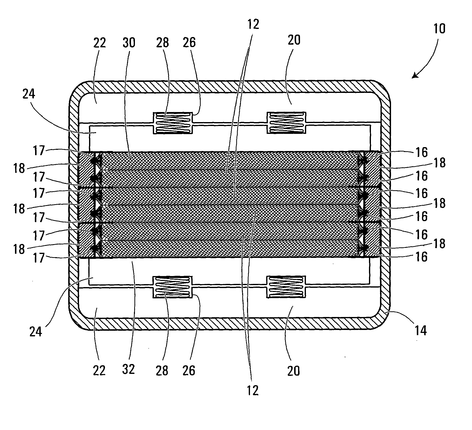
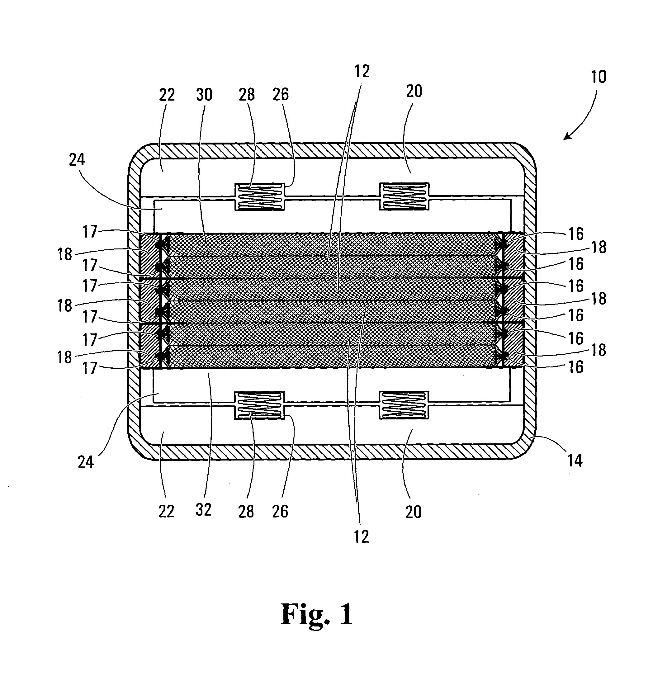
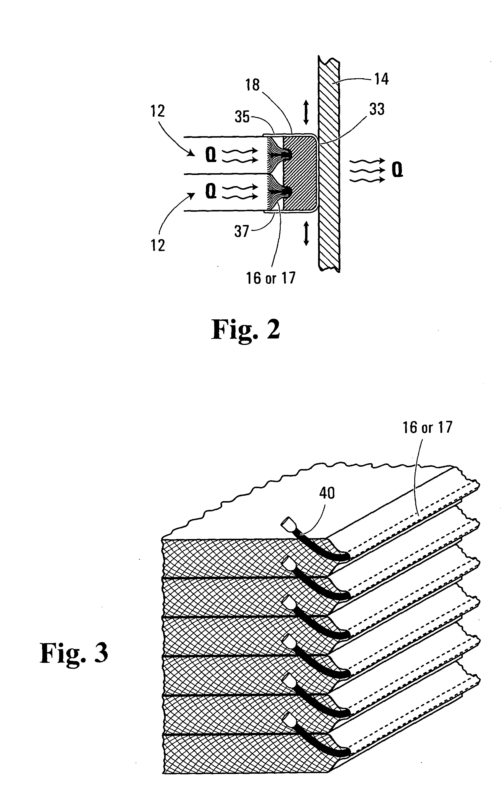
[0026] In FIG. 1, there is shown for illustration purposes a specific, non-limiting example of implementation of a polymer battery 10 configuration comprising a prismatic assembly of electrochemical cells 12 stacked together. The polymer battery 10 comprises a housing or enclosure 14, a series of stacked electrochemical cells 12 each comprising a plurality of individual electrochemical laminates connected together in parallel by current collecting terminals 16 and 17, resilient heat sink pads 18 positioned adjacent the current collecting terminals 16 and 17 and in intimate mechanical contact with the terminals 16 and 17, and a pressure system 20 located at each end of the electrochemical cells stack and adapted to maintain under pressure the electrochemical cells 12. Individual electrochemical laminates generally comprise an anode layer, a polymer electrolyte separator layer, a cathode layer and at least one current collector. Each electrochemical laminate typically has a thickness ...


PUM

PropertyMeasurementUnit
thicknessaaaaaaaaaa
thicknessaaaaaaaaaa
thicknessaaaaaaaaaa

Abstract

A polymer electrochemical generator having a plurality of electrochemical cells, each including at least one current collecting terminals, as well as a resilient heat sink material positioned adjacent and in mechanical contact with the current collecting terminals. The resilient heat sink material is electrically resistive and thermally conductive. A thermally conductive structural housing having walls encloses the plurality of electrochemical cells and the resilient heat sink material. The walls of the structural housing are positioned adjacent the resilient heat sink material and are in thermal contact therewith, for dissipating thermal energy generated by the plurality of electrochemical cells.

Description

FIELD OF THE INVENTION [0001] The present invention relates generally to polymer batteries and more specifically to a thermal exchange apparatus for polymer batteries. BACKGROUND OF THE INVENTION [0002] Rechargeable batteries manufactured from laminates of solid polymer electrolytes and sheet-like anodes and cathodes display many advantages over conventional liquid electrolyte batteries. These advantages include having a lower overall battery weight, a higher power density, a higher specific energy and a longer service life, as well as being environmentally friendly since the danger of spilling toxic liquid into the environment is eliminated. [0003] Solid polymer electrochemical cell components include positive electrodes, negative electrodes and a separator material capable of permitting ionic conductivity, such as a solid polymer electrolyte sandwiched between each anode and cathode. The anodes (or negative electrodes) and the cathodes (or positive electrodes) are made of material...

Claims


Application Information

Patent Timeline
Patent Type & Authority Applications(United States)
IPC IPC(8): H01M8/04H01M8/10H01M10/04H01M10/0525H01M10/0565H01M10/36H01M10/50H01M50/528
CPCH01M2/00H01M2/0217H01M2/22H01M10/0413H01M10/0463H01M10/0525Y02E60/122H01M10/5004H01M10/5032H01M10/5046H01M10/5067H01M10/5075H01M10/0565H01M10/6563H01M10/647H01M10/6551H01M10/6567H01M10/613Y02E60/10H01M50/00H01M50/103H01M50/528Y02P70/50
Inventor FOGAING, MICHAELLAGUE, FREDERICGEOFFROY, SEBASTIENGILBERT, GUY
Owner BATHIUM CANADA
Why Eureka
Try Eureka