Flow sensor

a flow sensor and flow sensor technology, applied in the direction of volume/mass flow measurement, measurement devices, instruments, etc., can solve the problems of easy damage to the device by mechanical strain, sensitiveness of the device, and undesired diffusion of substances affecting the properties of the device,

Inactive Publication Date: 2004-11-09
SENSIRION HLDG
View PDF21 Cites 121 Cited by
  • Summary
  • Abstract
  • Description
  • Claims
  • Application Information

AI Technical Summary

Problems solved by technology

Semiconductor devices of this type are, however, sensitive.
In contact with liquids, an undesired diffusion of substances affecting the properties of the device occurs easily.
Furthermore, mechanical strain can damage the device.
Hence, the semiconductor devices have to be protected in complicated manner, e.g. by protection layers.

Method used


Image

  • Flow sensor
  • Flow sensor
  • Flow sensor

Examples


first embodiment

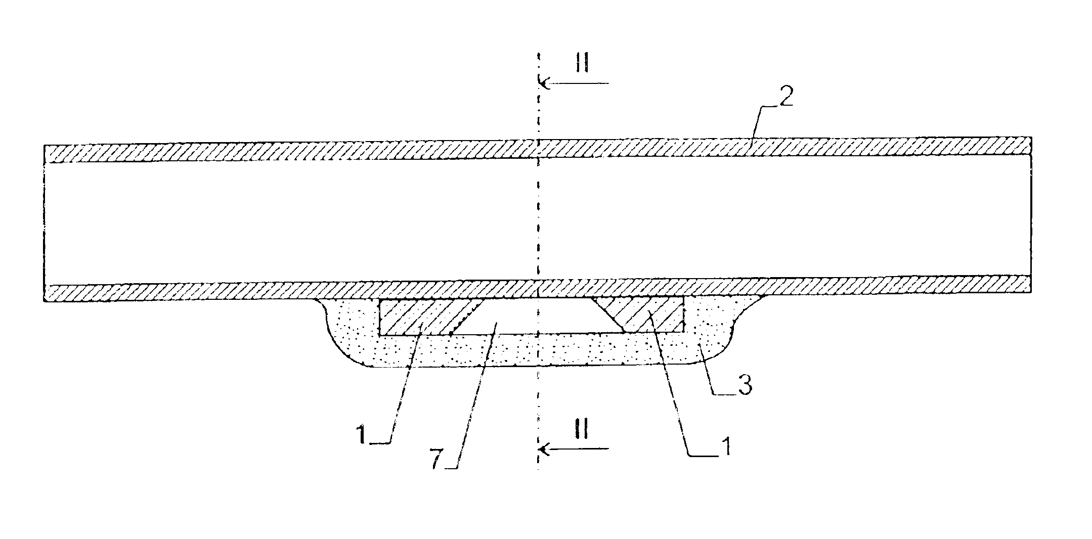
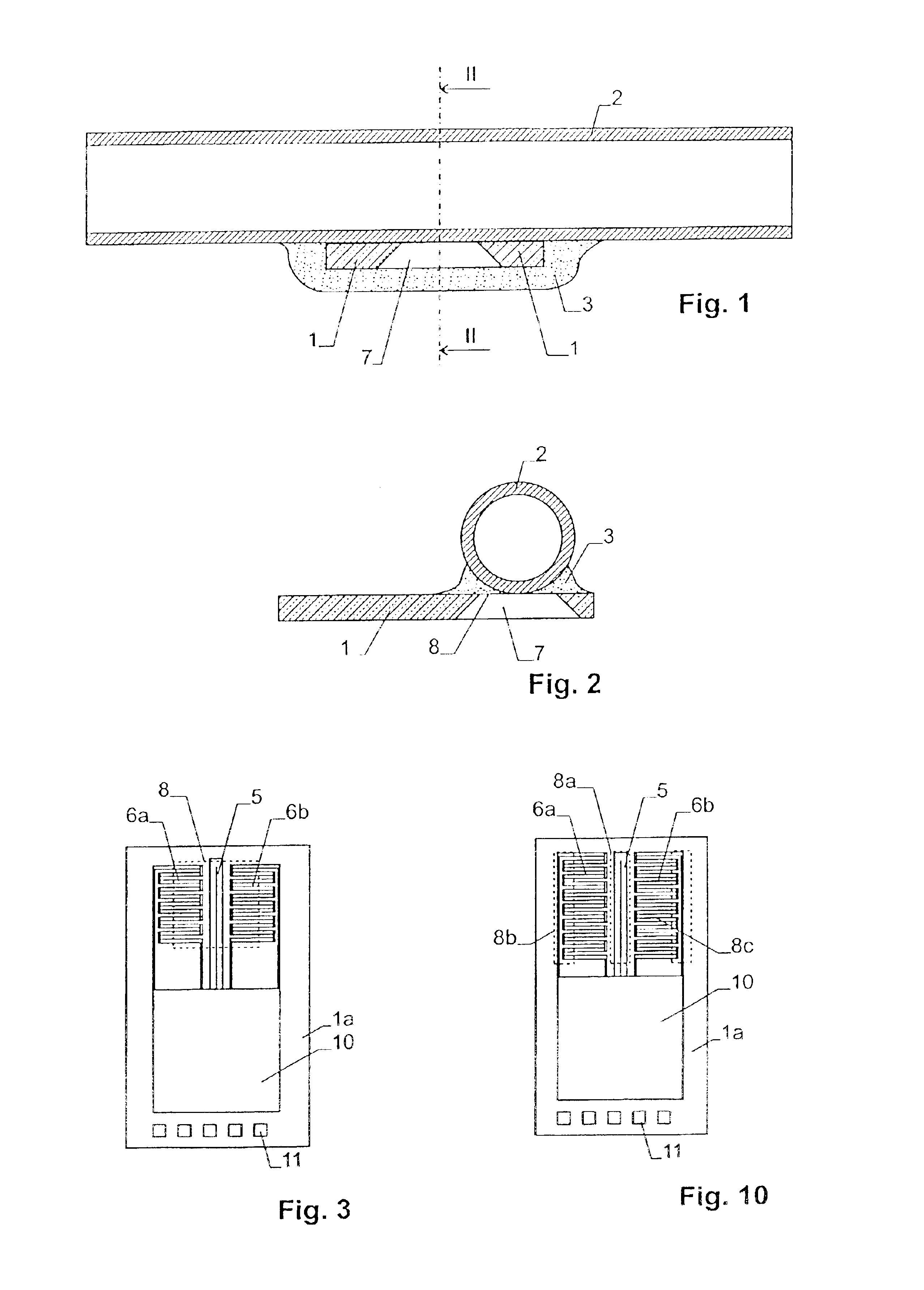
The basic design of the flow sensor results from the first embodiment illustrated in FIGS. 1-3. It consists of a semiconductor device 1, which is arranged at the exterior side of a tube section 2, through which the liquid to be measured is flowing. For affixing semiconductor device 1 to tube section 2, a hardened adhesive mass 3 is provided in this embodiment.

As it can especially be seen from FIG. 3, semiconductor device 1 consists of a substrate 1a, on which a heat source 5 in the shape of an integrated resistor is arranged. Before and after heat source 5, as seen in flow direction, two temperature sensors 6a, 6b are provided. In the present preferred embodiment the temperature sensors are designed as thermopiles.

An opening 7 is etched out of substrate 4, which opening is covered by a thin dielectric membrane 8. The heat source 5 as well as the heat source side contact rows of the thermopiles 6a, 6b are located on membrane 8. By means of this arrangement the thermal conductivity be...

second embodiment

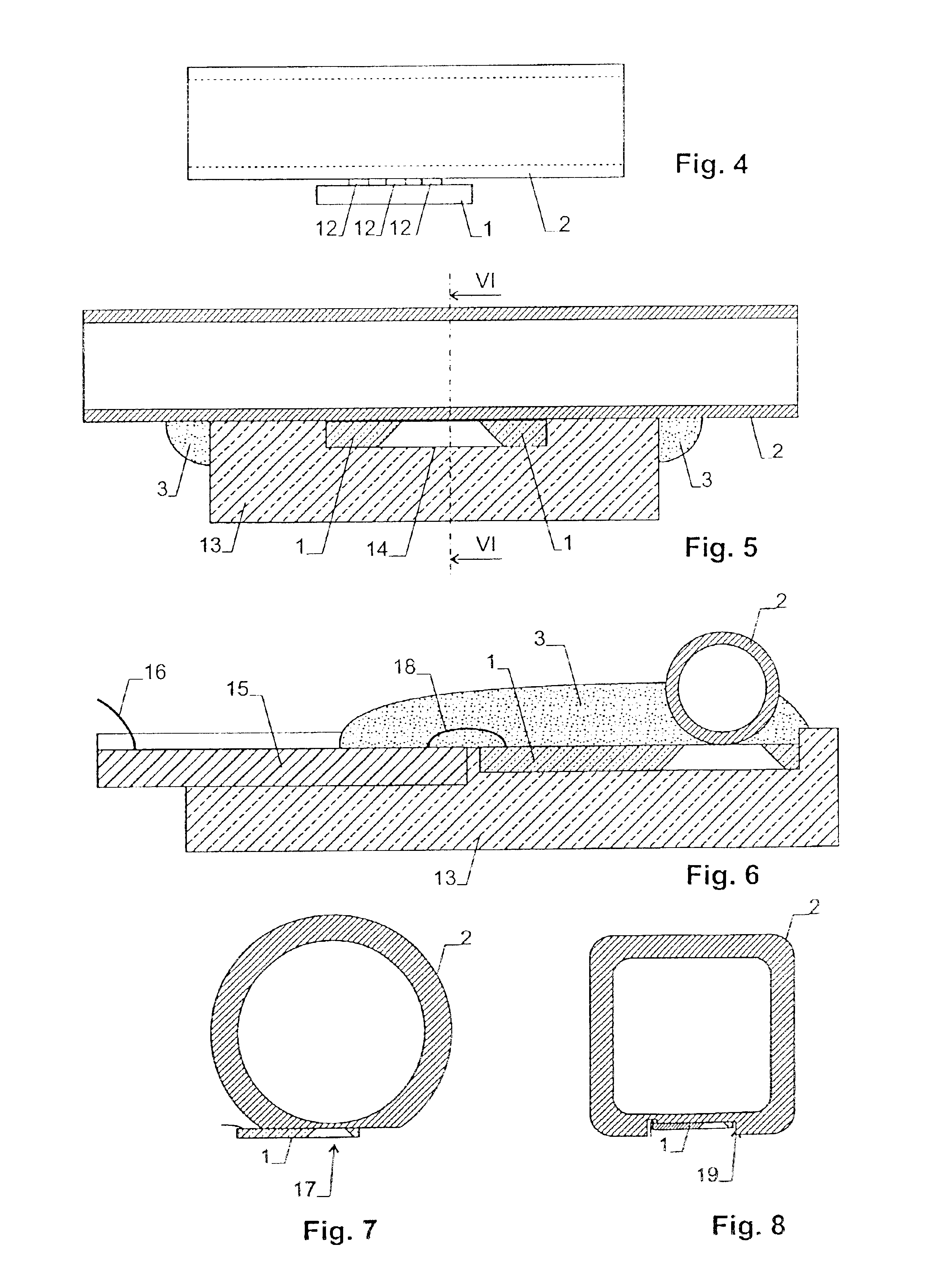
the invention is illustrated in FIG. 4. Here, semiconductor device 1 is not directly abutting against the exterior side of tube section 2. Rather, three heat conducting elements 12 are arranged between semiconductor device 1 and tube 2. They can e.g. be "metal bumps", i.e. projections of metal, preferably gold or copper, which lie on top of the inner contact rows of the thermopiles 6a, 6b and heating 5 and form a thermal contact with each of them. The arrangement of FIG. 4 has the advantage that the semiconductor device 1 is in thermal contact with tube section 2 at well defined places only.

The semiconductor device of FIG. 4 can, as the one according to FIG. 1, also be covered by an adhesive mass.

FIGS. 5 and 6 show a further embodiment of the invention, where semiconductor device 1 is protected by a housing 13. Housing 13 consists preferably of plastics and possesses e.g. a suited recess for receiving semiconductor device 1. Semiconductor device 1 is connected to a printed circuit 1...


PUM


Abstract

The flow sensor comprises a semiconductor device (1) on which a heat source and, symmetrically thereto, two temperature sensors are arranged. The semiconductor device (1) is arranged on an exterior side of a tube section (2), and a liquid, the flow velocity of which has to be measured, is led through the tube section (2). The temperature sensors and the heat source are in thermal contact with the exterior side of the tube section (2). It has been found that such an assembly allows to carry out flow measurements with high accuracy and sensitivity.

Description

This application claims the priority of the Swiss applications 0871 / 00 and 1160 / 00, filed May 4 and Jun. 13 2002, respectively, and the disclosure of which is incorporated herein by reference in its entirety.The invention relates to a flow sensor for a liquid as well as to a method for its production.STATE OF THE ARTIt has been known to measure the flow velocity and the mass flow, respectively, of a fluid with a semiconductor device, on which a heat source and at least one temperature sensor are arranged. The flow leads to a change of the temperature distribution of the heat source, which can be measured by means of the temperature sensor or temperature sensors.Semiconductor devices of this type are, however, sensitive. In contact with liquids, an undesired diffusion of substances affecting the properties of the device occurs easily. Furthermore, mechanical strain can damage the device. Hence, the semiconductor devices have to be protected in complicated manner, e.g. by protection l...

Claims


Application Information

Patent Timeline
Patent Type & Authority Patents(United States)
IPC IPC(8): G01F1/684
CPCG01F1/6847G01F1/6845
Inventor MAYER, FELIXHORNUNG, MARK RAINERVANNA, RALPH STEINER
Owner SENSIRION HLDG
Why Eureka
Try Eureka