
Portable high-temperature, high-pressure washing plant

a high-pressure washing and portable technology, applied in the field of carpet cleaning, can solve the problems of people being exposed to an enormous amount of foreign matter, unable to keep clean, and unable to meet the needs of cleaning,

Inactive Publication Date: 2004-01-13
BLUE LINE EQUIP
View PDF19 Cites 125 Cited by
  • Summary
  • Abstract
  • Description
  • Claims
  • Application Information

AI Technical Summary

Benefits of technology

A PTO for mechanical power can run full time at the engine or transfer case without gear engagement and disengagement. Instead, a PTO clutch is engageable downstream from the transmission or transfer case in the power train. Thus high, positive displacement, mechanical power can be output reliably from the transmission or transfer case, not jury-rigged from the fan belt. The downstream positioning of the clutch permits the PTO to be continuously engaged, thereby avoiding the shifting frequency problems that might otherwise be encountered. Also, any constantly rotating PTO shaft provided in a production truck can be accessed and used.
Increased cleaning fluid temperatures enable faster and more thorough cleaning of carpets and other surfaces. In addition, carpet dries faster when cleaned with superheated steam or water. The enhanced vacuum power of the current invention allows multiple operators with separate lines and wands to work from a single supply system on one truck. This decreases cleaning time, cuts labor costs, and minimizes inconvenience to customers. Substantially lower repair costs and downtime flow from a simpler design. In addition, the current invention provides a `multi-function" (e.g. steam cleaning and pressure washing) machine in accordance with new and newly proposed restrictions on hazardous waste dumping, promulgated by the EPA and other governmental agencies.
Furthermore, more space and a higher weight capacity are available to support larger wastewater recovery tanks, thereby reducing the likelihood that hazardous materials will be dumped on streets or in storm drains accidentally or in relief valve operation. Less equipment set-up time is required because the vehicle has adequate space for cleaning fluid, tools, and other accessories. Since the vehicle carries its water on board, operators are free of the need to locate and connect to a water source (often an inadequate source) near each job site. The apparatus and method of the present invention are the only known means of eliminating the need to jettison needed water as a means of temperature control in co-generator heating systems. Since cleaning water is never jettisoned as a means for temperature control, the supply lasts longer and the waste tank does not fill up as fast. Since the exhaust flow is diverted to control overheating, the top-end cleaning fluid temperature is regulated without resorting to any manipulation of the heated water or heat exchanger performance.

Problems solved by technology

Ever since carpets came into common use, people have wrestled with the difficulty of keeping them clean.
Carpet, unlike other fabric in household use, is exposed to an enormous amount of foreign matter such as dirt, grass, leaves, sand, dust, mud, animal hair, and spilled food.
The problem is compounded by both the permanent (e.g. wall-to-wall) installation of carpet and the length of fibers found in many carpets.
Conventional washing and cleaning processes remain ineffective.
Moreover, the energy requirements for the phase change to steam simply cannot be met by most heating plants for the purpose.
Excess water tends to damage carpets by soaking into areas over time, causing over-wetting.
Over-wetted textiles often show signs of reduced strength, mildew, and delamination, a process in which the carpet takes on a rippled appearance due to separation of primary and secondary backings.
However, increasing chemical concentrations creates a whole new series of problems.
Also, cleaning chemicals are known to leave residues that cause carpet to re-soil at an accelerated rate by adhering to soiling materials.
Since the effectiveness of any hot-water extraction method depends greatly on the fluid temperature, an inconsistent fluid temperature results in a carpet that appears patchy because it is cleaner in some places than in others.
In addition, temperatures in excess of 240.degree. F. can permanently yield synthetic fibers, thereby causing fiber memory loss and ruining the pile texture of carpet.
As a result, they provide inferior cleaning temperatures, typically in the range of 80.degree. to 120.degree. F. at the carpet surface.
Portable machines are notorious for excessive use of chemicals.
High chemical concentrations are required to clean textiles because of comparatively low cleaning temperatures.
Each has its own set of performance and maintenance problems.
The result is that the best heat exchangers and transfer times do not produce a maximum cleaning fluid temperature above 195.degree. F. in the heat exchanger, which temperature is substantially reduced by the time fluid reaches a carpet surface.
Since they take energy from the coolant that passes through the vehicle radiator, they provide an inconsistent, and still too low fluid temperature at the carpet surface.
A lot of energy is available from the engine coolant, but at a low thermodynamic availability.
Unfortunately, large, high torque (e.g. V-8), gasoline-powered engines, were not designed to run stationary at 1500 RPM for hours at a time just to drive the fan belt while carpet cleaners perform their work.
Without a consistent convective air flow, gasoline engines idling for lengthy periods of time tend to create enormous amounts of radiant heat that which destroys electrical components and leads to reliability problems.
Although sometimes a significant improvement over portable systems, and slide-in units, the integrated, truck-mounted systems can also dump substantial waste heat and vibrational energy into the vehicle.
They tend to destroy the vehicle body, wear out the engine, and damage its electrical equipment and mechanical connections.
These problems have been exacerbated during recent years by the introduction of electronic components and controls about the cab and engine bay of modem vehicles.
The result is a continuing degradation and failure of electrical and electronic components.
Such failures regularly render the engine inoperative until the failed component is replaced.
As with direct-drive systems, the equipment compartment (bed) and cab of a van become very hot when the engine is run in stationary mode with only the confined, standard, inadequate cooling system.
The unit is also nearly impossible to isolate mechanically from the body of the vehicle.
As a practical matter, slide-in systems literally self-destruct during a comparatively short and very unreliable life.
Thus, these self-contained, slide-in systems are generally regarded as even more problematic and unreliable than direct drive systems.
Poor reliability and durability should come as no surprise because of the extraordinary amounts of heat rejected by the engines into the environment.
Moreover, the net thermal energy output is still typically too low to support the amount of water flow required for a high rate of cleaning.
When the engines of slide-in units have been selected to have thermal outputs to support higher temperatures at the required water flow rates, the fuel efficiency is still extremely poor, and the environmental heat rejection problem is even more serious.
However, for a small engine (e.g. slide-in unit), the mass flow rate of exhaust is very low, so overall heat transferred to the cleaning fluid is also low.
Despite their increased mechanical power, currently available direct drive machines remain incapable of maintaining a consistently high cleaning fluid temperature.
However, use of auxiliary burners, such as propane, kerosene, diesel, and electric burners, has been declining in recent years.
External heating is cumbersome, inconvenient to set-up, expensive, and possibly even dangerous due to the possibility of fire or overheating.
However, some carpet-cleaning professionals persist in using external heating machines because the co-generating devices (capturing waste heat from a thermodynamic engine to use as process heat) typically cannot produce a sufficiently high temperature (over 170.degree. F. at the carpet, over 195.degree. F. in the system), sufficient efficiency, nor an acceptable level of reliability.
However, stationary engines for comparatively unregulated, limited use, such as those found in slide-in systems, have not been optimized to the same extent.
As a result, larger slide-in motors consume a great deal of fuel without providing a comparable amount of power or rejected heat required for process heating.
Nevertheless, perhaps the most serious problem for co-generation systems is the failure of their control systems.
Valves, whether driven by solenoids or vacuum, quickly foul with calcium, lime, magnesium, and other precipitates.
Meanwhile, the high environmental temperatures inherent in such systems destroy the electrical and electronic control components.
Direct drive, co-generation machines lack any safe, reliable, and convenient method for conveying the cleaning fluid and the exhaust through a heat exchanger.
Bringing an engine exhaust line into an enclosed rear cabin of a vehicle, together with the pumping equipment and cleaning fluid, is dangerous.
An inevitable opening or leak in the exhaust pipe would fill the vehicle with exhaust gases, which are toxic, corrosive, and possible even highly combustible.
Likewise, extending a cleaning fluid line outside the cabin of a van or other service vehicle to access and exhaust line is not a viable solution.
Any water-based cleaning fluid left in the line in cold weather will freeze when the engine is not running, bursting the line.
If an operator stops to move furniture, reposition equipment, or make a dry pass to vacuum up excess cleaning fluid, the flow rate of cleaning fluid through a washing plant will slow or stop.
The resulting temperatures and pressures can harm carpet, destroy equipment, and cause personal injury.
Solutions expelling overheated cleaning fluid either out of the system or into a waste tank when it becomes too hot are inadequate.
One drawback of such a safety device is that the cleaning fluid must be replenished before cleaning can resume.
Anything vented to the holding tank reduces capacity, and must be dumped along with the collected soiled cleaning fluid.
Thus, dump valve systems are inconvenient and potentially harmful to the environment.
Every day, thousands of gallons of cleaning fluid are wasted in the carpet cleaning industry due to cleaning fluid venting performed in the name of temperature regulation.
Devices that shut down the system are similarly inconvenient, and often not safe.
A failure in a temperature regulating mechanism can allow the fluid temperature to continue rising to dangerous levels.
Meanwhile, the electrical and electronic control elements, such as sensors, solenoids, and valves, used to detect excessive temperatures and bleed off cleaning fluid or shut down the system are prone to failure.
Control orifices can be very small and are subject to clogging from calcium, lime, and magnesium deposits from the cleaning fluid.
The high temperatures involved accelerate the buildup of deposits and can damage the wire coils and insulation, causing failure in items such as solenoids.
Valve failures can cause catastrophic failure of the entire system.
One more problem that plagues known washing plants involves the method by which mechanical power is transferred from the vehicle engine to the pumps and heaters.
No carpet cleaning system is known to use any power takeoff coming directly from the engine or from a transmission or transfer case.
Transmissions are delicate and expensive.
Just as engines are overworked, and improperly worked in such an application, gear systems would be overworked and be subject to mechanical failures due to repeated engagement and disengagement of the PTO gears if operated to control connection of mechanical systems to engine power.
In addition, carpet dries faster when cleaned with superheated steam or water.

Method used


Image

  • Portable high-temperature, high-pressure washing plant
  • Portable high-temperature, high-pressure washing plant
  • Portable high-temperature, high-pressure washing plant

Examples


Embodiment Construction

It will be readily understood that the components of the present invention, as generally described and illustrated in the figures herein, could be arranged and designed in a wide variety of different configurations. Thus, the following more detailed description of the embodiments of the system and method of the present invention as represented in the figures, is not intended to limit the scope of the invention. The scope of the invention is as broad as claimed herein. The illustrations are merely representative of certain, presently described embodiments of the invention. Those presently described embodiments of the invention will be best understood by reference to the drawings, wherein like parts are designated by like numerals throughout.

Those of ordinary skill in the art will appreciate that various modifications to the details of the figures may easily be made without departing from the essential characteristics of the invention. Thus, the foregoing description of the invention,...


PUM


Abstract

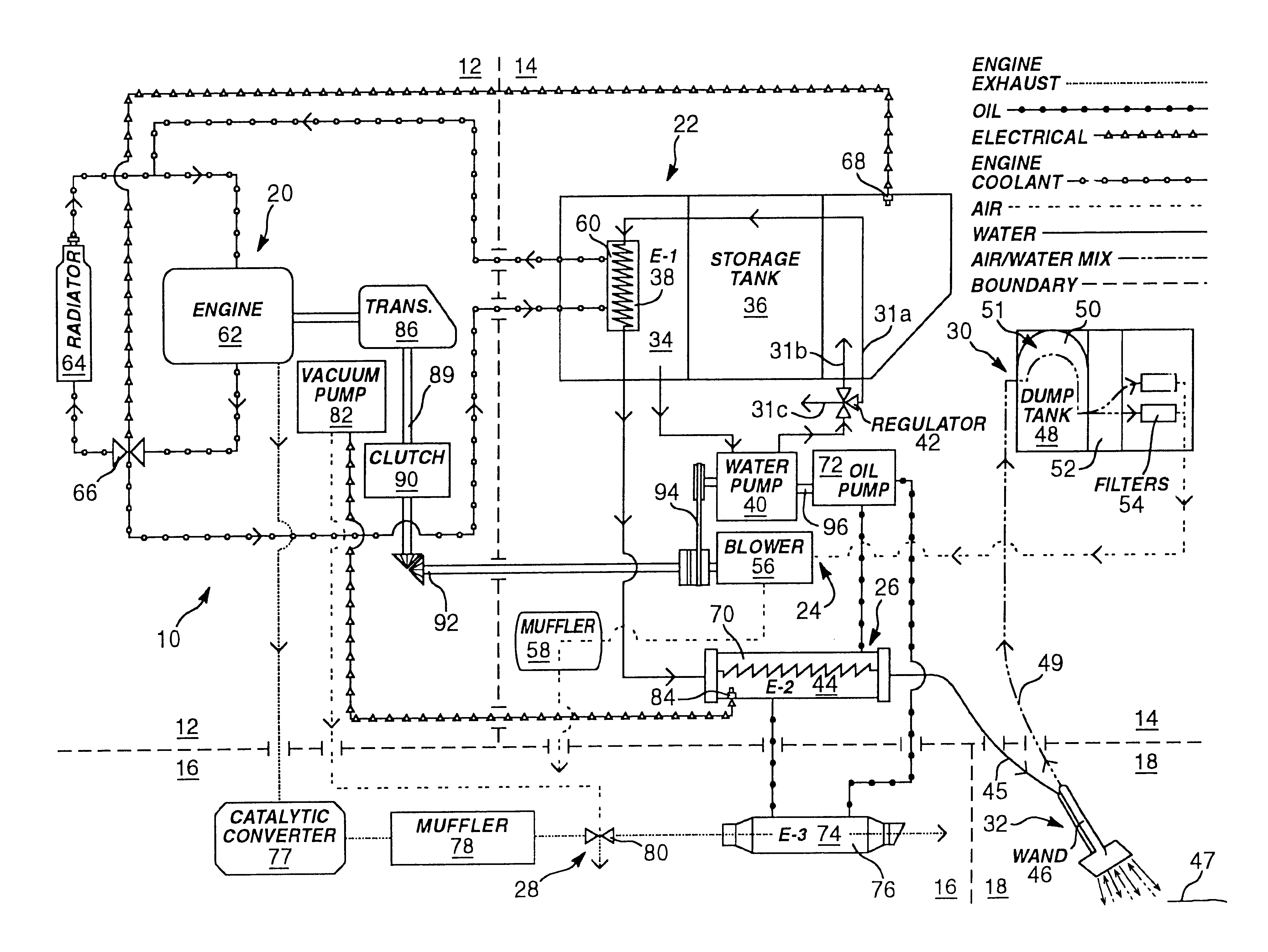
A washing system for high temperature cleaning applications, such as carpet-cleaning, is disclosed that provides a consistent cleaning fluid temperature. The washing system utilizes multiple heat exchangers and multiple heat paths. The heating and power source is provided by a medium duty, diesel cycle engine. Multi-stage heating involves heat transfer from the engine's coolant to the cleaning fluid and heat transfer from the exhaust of the engine to the cleaning fluid via an intermediate medium. The system also includes a fluid clutch used to engage a power takeoff from the engine to operate the pump and blower of the washing plant. A failsafe source cutoff diverts the exhaust flow from thermal contact with an intermediate heat transfer oil.

Description

1. Related ApplicationThe present application is related to and claims priority to PCT Application Serial No. PCT US99 / 29770, International Filing Date of Dec. 15, 1999, and Priority Date of Dec. 17, 1998, which is incorporated herein by reference for all purposes.2. The Field of the InventionThis invention relates to carpet cleaning generally, and more particularly to portable, self-contained pumping and heating systems for carpet cleaning. More particularly still, the invention relates to a cleaning system that uses heated cleaning solution where the heat is derived from secondary heat of a primary heat-generating engine, which also provides mechanical force used to deliver and remove the cleaning solution during cleaning.3. The Background ArtEver since carpets came into common use, people have wrestled with the difficulty of keeping them clean. Carpet, unlike other fabric in household use, is exposed to an enormous amount of foreign matter such as dirt, grass, leaves, sand, dust,...

Claims


Application Information

Patent Timeline
IPC IPC(8): A47L11/00A47L11/34B60P3/14F01N5/00F01N5/02F02G5/00F28D15/00
CPCA47L11/34A47L11/4011A47L11/4083A47L11/4088B60P3/14F01N5/02F02G5/00F28D15/00F28D21/0003Y02E20/14Y02T10/16Y02T10/166Y02T10/12
Inventor YORK, SHAWN L.
Owner BLUE LINE EQUIP
Learn More