Magnus rotor

a technology of rotor and rotor body, which is applied in the direction of air-flow influencers, marine propulsion, vessel construction, etc., can solve the problems of affecting operation or making it impossible, affecting the efficiency of the magnus rotor drive, and affecting the surrounding area, so as to achieve greater or and faster heating and thawing. , the effect of increasing the efficiency

Active Publication Date: 2013-09-19
WOBBEN PROPERTIES GMBH
View PDF6 Cites 5 Cited by
  • Summary
  • Abstract
  • Description
  • Claims
  • Application Information

AI Technical Summary

Benefits of technology

[0010]It is advantageous to provide a heating device in the interior of the carrier, to cause that air to be heated and to allow the heated air to rise into the region outside and above the carrier to the rotor, through at least one opening, as that heated air heats the rotor from the interior and thereby ice which clings to its outside wall can be thawed off. An iced-up Magnus rotor can be rendered operative again by virtue of that thawing action as a Magnus rotor, to the outside of which ice is adhering, should not be operated. Thus the ice clinging to the rotor can represent a considerable additional mass which would have to be additionally driven and which worsens the efficiency of the Magnus rotor drive. In addition the ice can cling asymmetrically to the outside wall and in that way generate an unbalance which can adversely affect operation or make it impossible. There is also the risk that in operation ice clinging to the rotor is detached from the outside wall of the Magnus rotor and thrown off same, whereby the surrounding area can be endangered by the pieces of ice which are flung away. It is therefore necessary, for safety reasons and to restore operation of the Magnus rotor, to provide a possible way of being able to thaw an iced-up Magnus rotor as quickly as possible.
[0011]In an aspect of the invention it is provided that the heating device is connected to the carrier openings by way of at least one air guide means in such a way that the air heated by the heating device can be discharged into the intermediate space between the carrier and the rotor. That provides that the heated air is discharged as completely as possible and not just partially into that intermediate space, which is the case if the heated air were to be discharged from the heating device into the interior of the carrier and were to only partly rise up therefrom into that intermediate space. That can achieve higher efficiency in terms of utilizing the heat of the heated air for heating and thawing the rotor. Furthermore additional heating of the space inside the carrier may be undesirable so that in that respect also it is advantageous for the heated air to be discharged as completely as possible into the intermediate space between the carrier and the rotor.
[0013]In an aspect of the invention the heating device has a plurality of air guide means and / or the carrier has a plurality of openings and / or the connecting element has a plurality of openings. That on the one hand provides that air exchange upwardly into the rotor is increased, whereby at the same time greater or faster heating and thawing of the outside wall of the rotor is achieved. On the other hand, the air flow is distributed more uniformly within the rotor through a plurality of openings so that this also provides for more uniform and thus faster heating and thawing.
[0016]In a further aspect of the invention the plurality of air guide means of the heating device and / or the plurality of openings of the carrier and / or the plurality of openings of the connecting element are provided on the periphery of the carrier and / or of the connecting element spaced as far as possible in the radial direction from the center line of the Magnus rotor. In that way the heated air can rise directly at the inside of the outside wall of the rotor and can thus deliver its heat energy thereto as quickly and as completely as possible.
[0018]In a further aspect of the invention the rotor is made from aluminum. As aluminum has thermal conductivity which is comparatively good, for example in comparison with steel, the thermal energy from the heated air can be absorbed comparatively well and quickly. That promotes rapid thawing of the rotor.
[0020]In a further aspect of the invention provided in the interior of the carrier is an electric motor. The heating device is fed with the electrical energy by way of electric lines, by way of which the electric motor is fed in operation of the Magnus rotor. That arrangement of the power supply, alternatively either to the electric motor or to the heating device, makes use of the fact that those two devices are not operated at the same time as thawing of the rotor is effected precisely when it cannot be driven by means of the electric motor, because of icing. Thus the installation complication and expenditure for the power supply of those two devices can be reduced as that electrical power supply can be effected to the greatest possible extent by way of the same lines.

Problems solved by technology

Thus the ice clinging to the rotor can represent a considerable additional mass which would have to be additionally driven and which worsens the efficiency of the Magnus rotor drive.
In addition the ice can cling asymmetrically to the outside wall and in that way generate an unbalance which can adversely affect operation or make it impossible.
There is also the risk that in operation ice clinging to the rotor is detached from the outside wall of the Magnus rotor and thrown off same, whereby the surrounding area can be endangered by the pieces of ice which are flung away.
Furthermore additional heating of the space inside the carrier may be undesirable so that in that respect also it is advantageous for the heated air to be discharged as completely as possible into the intermediate space between the carrier and the rotor.

Method used


Image

  • Magnus rotor
  • Magnus rotor
  • Magnus rotor

Examples


first embodiment

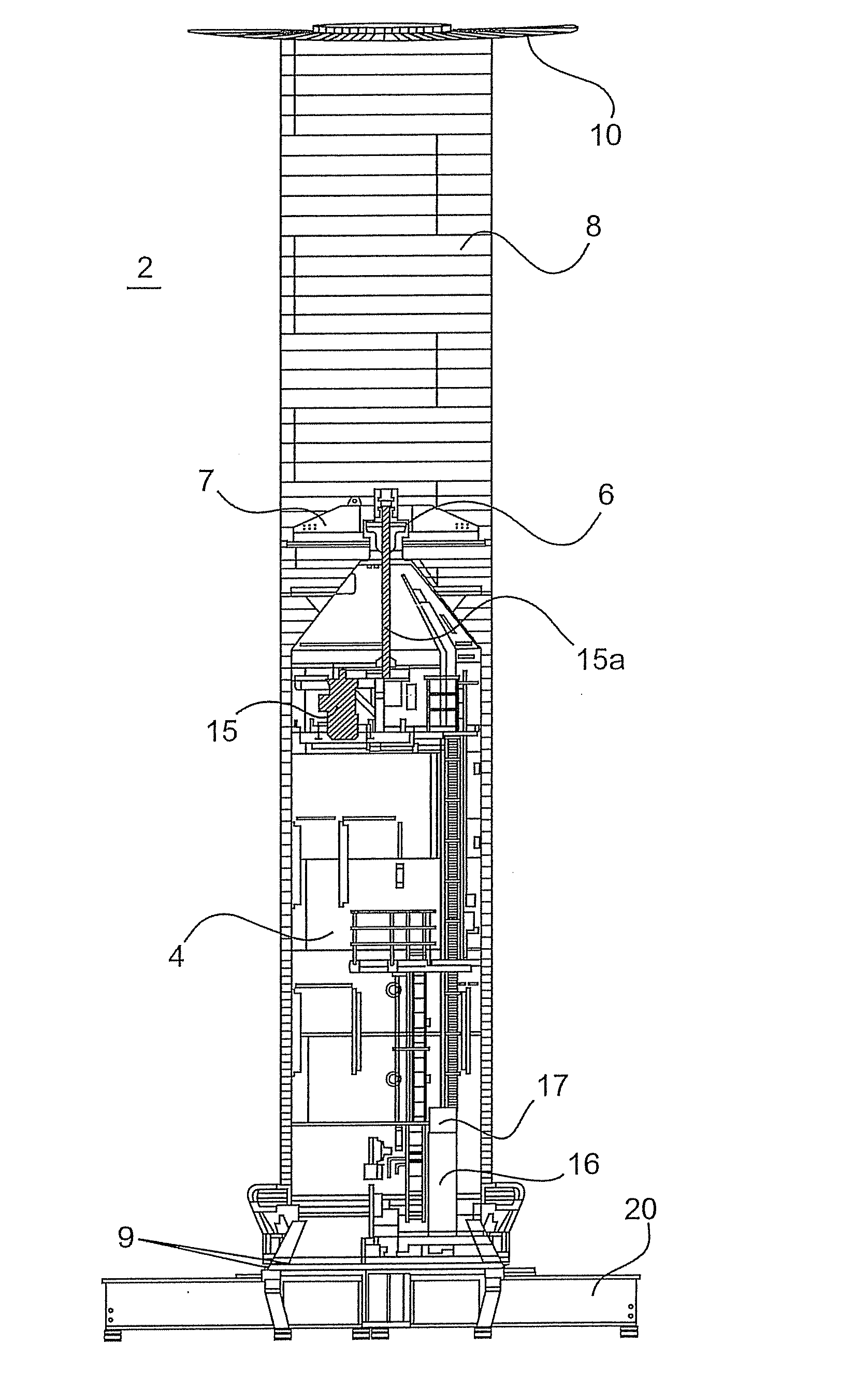
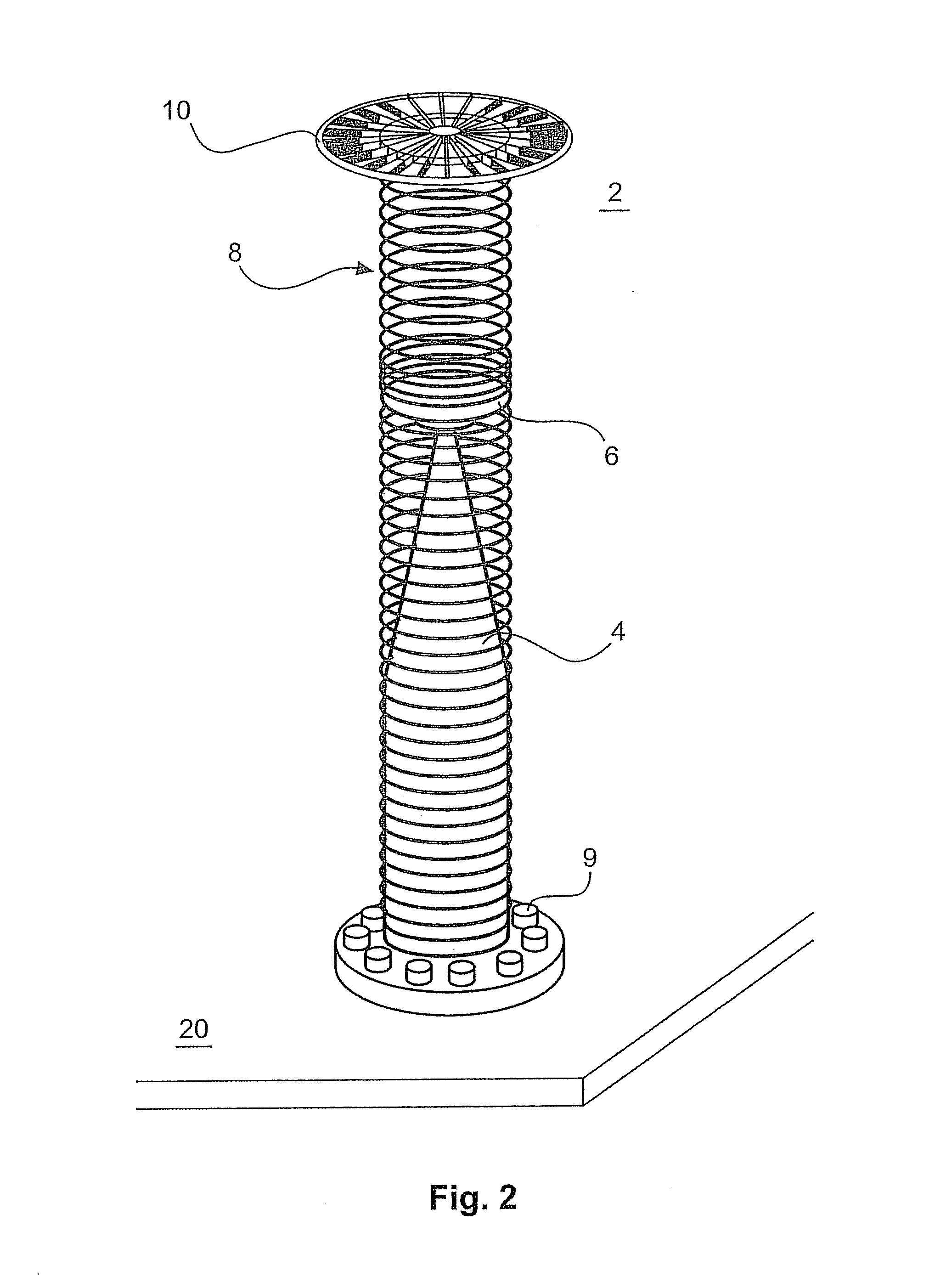
[0034]FIG. 4 shows a diagrammatic simplified side view of the Magnus rotor 2 with a heating device 3 in a The Figure shows the rotor 8 with end plate 10 and hub 7 as the parts which move in operation of the Magnus rotor 2. They are supported by way of the drive shaft 15a (not shown) which also rotates, on the bearing 6 of the carrier 4.

[0035]Shown in the interior of the carrier 4 as a heating device 3 is a fan heater 3 provided in the upper region of the carrier 4. The fan heater 3 produces hot air by drawing in air from the surroundings, that is to say from the internal space 50 in the carrier 4, and moving it for example past windings heated by electric current. In that case the air which is drawn in absorbs heat from the windings through which current flows. That heated air is then blown out by the fan heater 3. That is effected by way of at least one fan heater tube 3a connected to the discharge opening of the fan heater 3. That heating air tube 3a leads to at least one carrier...

second embodiment

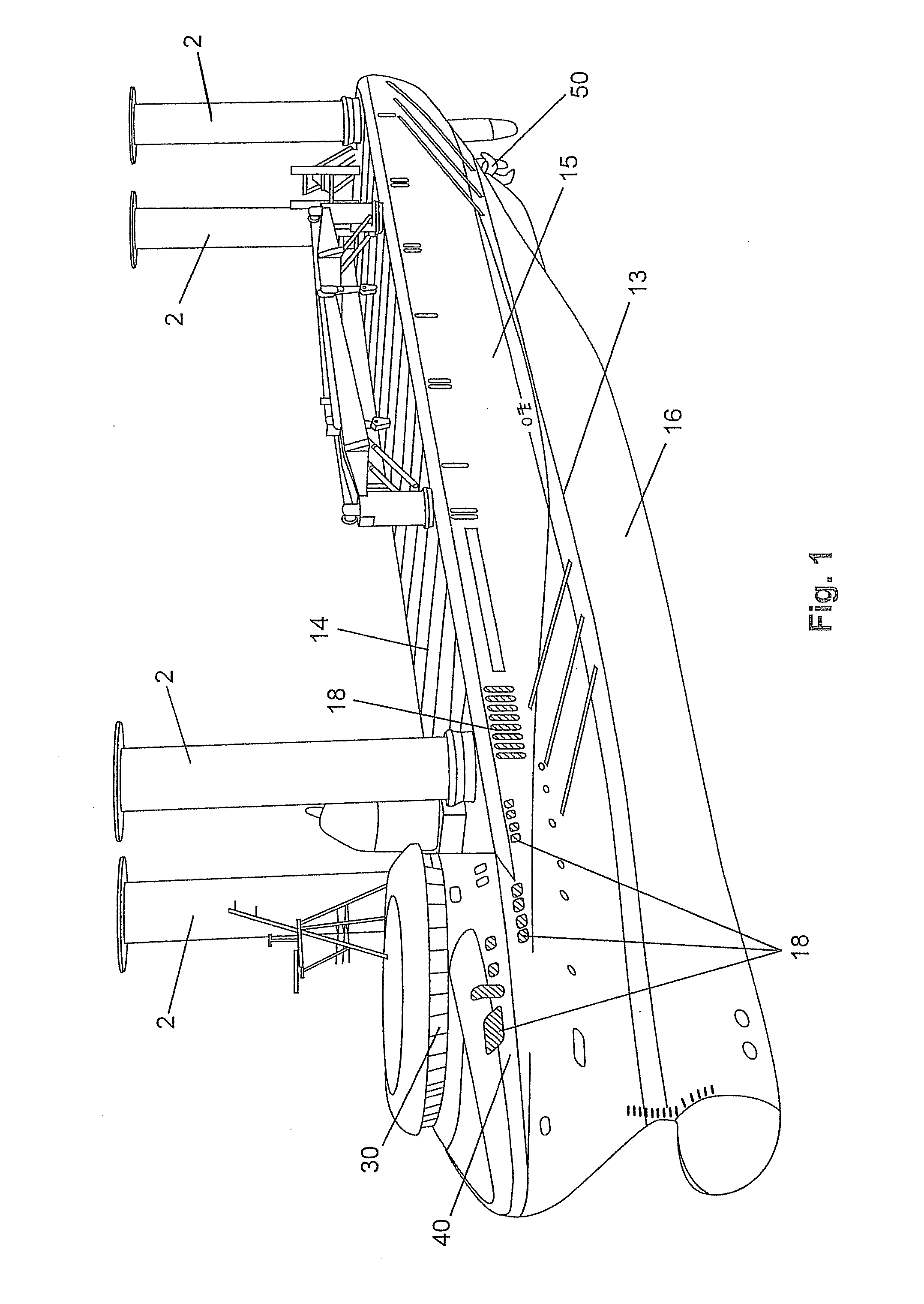
[0038]FIG. 5 shows a diagrammatic simplified side view of the Magnus rotor 2 with a heating device 3 in a FIG. 5 shows substantially the components of FIG. 4. It additionally shows the base plate 20 or the ship deck or the like, on which the Magnus rotor 2 is fixed by means of bolts or screws 9.

[0039]In this second embodiment the heating device 3 is arranged in the lower region of the carrier 4 and the fan heater tubes 3a and carrier openings 4a are provided in radially oriented relationship in the region of the Magnus rotor 2 in which the outside wall of the rotor 8 extends around the carrier 4. In this embodiment therefore the hot air is taken past the outside wall of the rotor 8 almost over the entire height of the rotor.

[0040]In that way the outside wall can also be heated and thawed out over its entire height. In this embodiment however a part of the heat of the hot air is already delivered in the lower region of the rotor 8 to the outside wall thereof so that only still warm ...


PUM


Abstract

The present invention concerns a Magnus rotor comprising a carrier arranged in the interior of the Magnus rotor, a rotor which in operation of the Magnus rotor rotates about the carrier, a bearing which carries the rotor on the carrier and a heating device provided for producing heated air in the interior of the carrier. The carrier has at least one opening at its outside, which connects the internal space in the carrier to the intermediate space between the carrier and the rotor in such a way that air can pass through between those two spaces.

Description

BACKGROUND[0001]1. Technical Field[0002]The present invention concerns a Magnus rotor.[0003]2. Description of the Related Art[0004]Magnus rotors are also referred to as Flettner rotors or sailing rotors.[0005]Magnus rotors are known in the state of the art. Particularly in the form of ship drives they are also known by the term Flettner rotor and equipping ships with such a Flettner rotor or Magnus rotor is described in the book ‘Die Segelmaschine’ by Klaus D Wagner, Ernst Kabel Verlag GmbH, Hamburg 1991.[0006]As such ship drives produce a propulsion force for the ship, with the co-operation of the rotary movement of the rotor and the wind flowing therearound, Magnus rotors can basically be used as ship drives wherever sufficient winds prevail. That is basically the case on all seas around the globe, that is to say in all climatic regions of the earth.[0007]In that respect however the seas and climatic regions of the earth have very different climatic conditions and weather conditio...

Claims


Application Information

Patent Timeline
Patent Type & Authority Applications(United States)
IPC IPC(8): B63H9/02
CPCY02T70/58B63H9/02Y02T70/5236
Inventor ROHDEN, ROLF
Owner WOBBEN PROPERTIES GMBH
Why Eureka
Try Eureka