Method for operating a fixed gas turbine, device for regulating the operation of a gas turbine and power plant

Inactive Publication Date: 2013-09-26
SIEMENS AG
View PDF8 Cites 3 Cited by
  • Summary
  • Abstract
  • Description
  • Claims
  • Application Information

AI Technical Summary

Benefits of technology

[0015]The proposed measures considerably reduce the demands on the supply pressure in the fuel network. As a result of the omission of the fuel compressor for relatively high fuel pressures at high fuel mass flow rates, high costs firstly for the procurement of such a high-powered fuel compressor and also for the operation thereof during the operation of the gas turbine can be eliminated.
[0017]According to a first advantageous method feature, the fuel volume in the fuel store is at a higher pressure than the supply pressure in the fuel network. It is preferable for the pressure in the fuel volume to be higher than the supply pressure in the fuel network by a factor of two to four. It is thus ensured that, when required, the fuel volume can be supplied without delay and in adequate quantities to the combustion in the combustion chamber. To achieve this, it is possible by means of a fuel compressor for fuel to be extracted from the fuel network and stored in the fuel store during the operation of the gas turbine and / or during the standstill phase. Since there is thus an adequately long time period available for the charging of the fuel store, it is possible to use a fuel compressor of relatively low power.
[0018]Furthermore, the method provides that, for the brief increase of the pilot fuel supplied to the combustion chamber via a pilot burner or via a plurality of pilot burners of the gas turbine, the fuel volume extracted from the fuel store is supplied to the pilot fuel still to be supplied to the combustion chamber. Undesired and unstable combustion states can be avoided in particular in this way.
[0019]If, instead of the fuel that can be extracted from the fuel network, another type of fuel is provided as a fuel volume in the fuel store, it is thus possible for the fuel store to be provided preferably in the form of one or more gas bottles. This eliminates the need to use a fuel compressor. Furthermore, with the different fuel type, if it is more reactive than the fuel to be supplied, the burn-out of the fuel to be supplied can be further improved. This increases the efficiency of the combustion, whereby the generally required thermal input—that is to say thermal power—is reduced. Since natural gas or synthesis gas is usually used as gaseous fuel, more reactive fuels are for example hydrogen or acetylene.
[0020]The reactivity may be described by a shorter ignition delay time. With an increasing fraction of the more reactive fuel volume in the fuel, the flame speed increases and the ignition delay time decreases. Both characteristic variables are therefore indicators that, through the admixing of hydrogen or acetylene, a considerably faster and more compact combustion can be realized, which, for a given residence time of the hot gas in the combustion chamber, yields an improvement in burn-out. It has been found here that a volume fraction of 10% to 30% of more reactive fuel in the overall fuel stream supplied is already adequate to increase the thermal efficiency and to give lower overall emissions of unburned fuel, in particular unburned hydrocarbons and carbon monoxide. The latter applies in particular to the pilot combustion if the main combustion—for example in the event of load shedding (load rejection)—is virtually or even completely stopped. At the same time, the improvement of the thermal burn-out for a given mass stream of the (pilot) fuel stream permits more stable overall thermo-acoustic behavior of the combustion.
[0026]The above-stated means preferably comprise a line which connects the fuel store to a line portion, in which line there is arranged an actuating element for opening and closing the line. To prevent pressure shocks in the merged fuel stream, it is possible for at least one jet pump to be provided in the fuel line system, to which jet pump can be supplied, as medium to be pumped, the fuel that can be extracted continuously from the fuel network and to which jet pump can be supplied, as pump fluid, the fuel volume that can be extracted from the fuel store, wherein the respective jet pump is connected at the outlet side to at least one burner of the gas turbine.

Problems solved by technology

This contradicts the requirement for efficient operability even with a reduced supply pressure in the fuel network.

Method used


Image

  • Method for operating a fixed gas turbine, device for regulating the operation of a gas turbine and power plant
  • Method for operating a fixed gas turbine, device for regulating the operation of a gas turbine and power plant
  • Method for operating a fixed gas turbine, device for regulating the operation of a gas turbine and power plant

Examples


Embodiment Construction

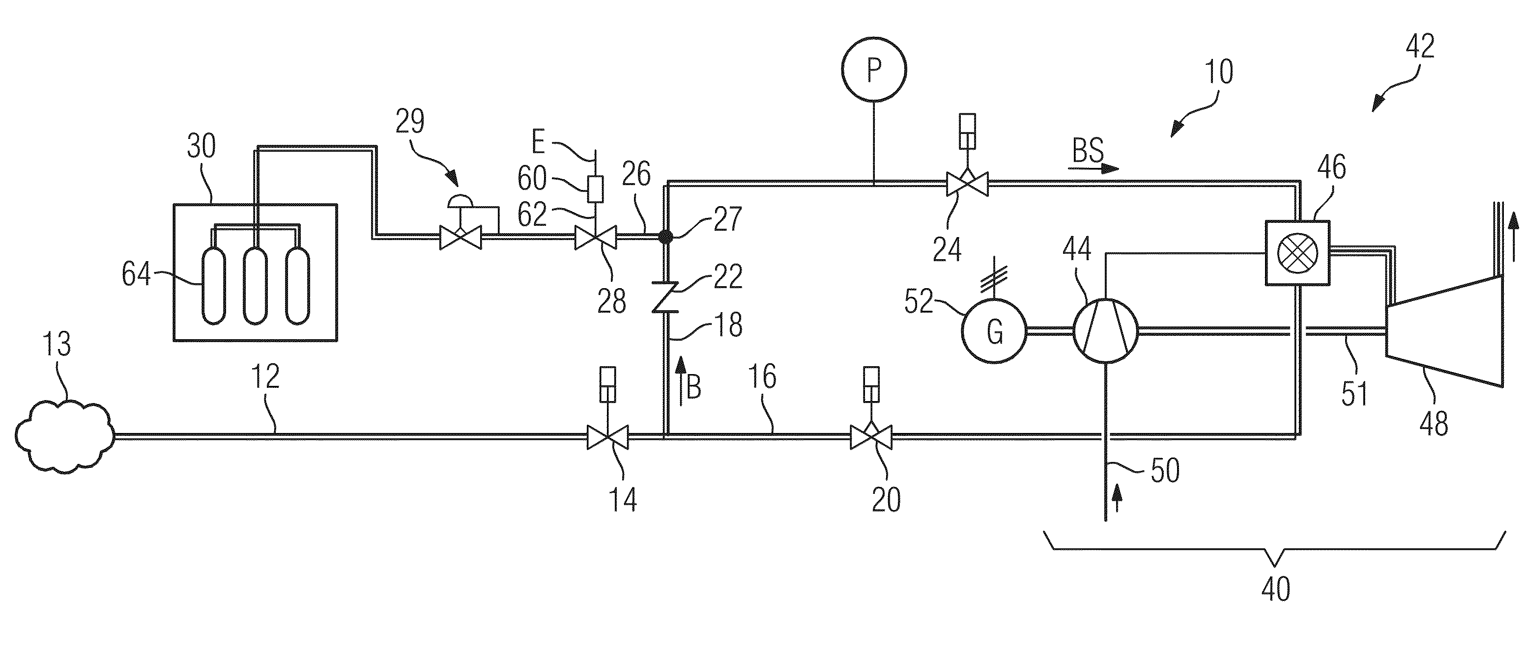
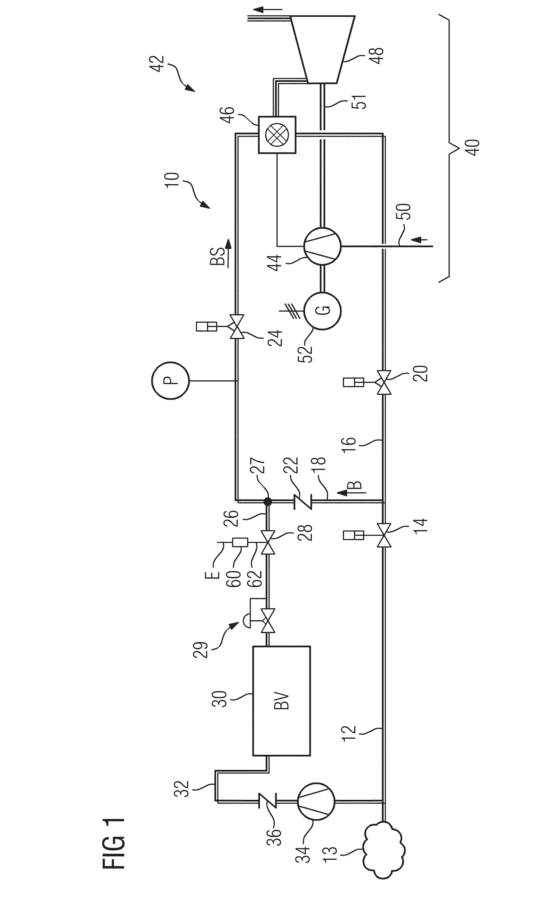
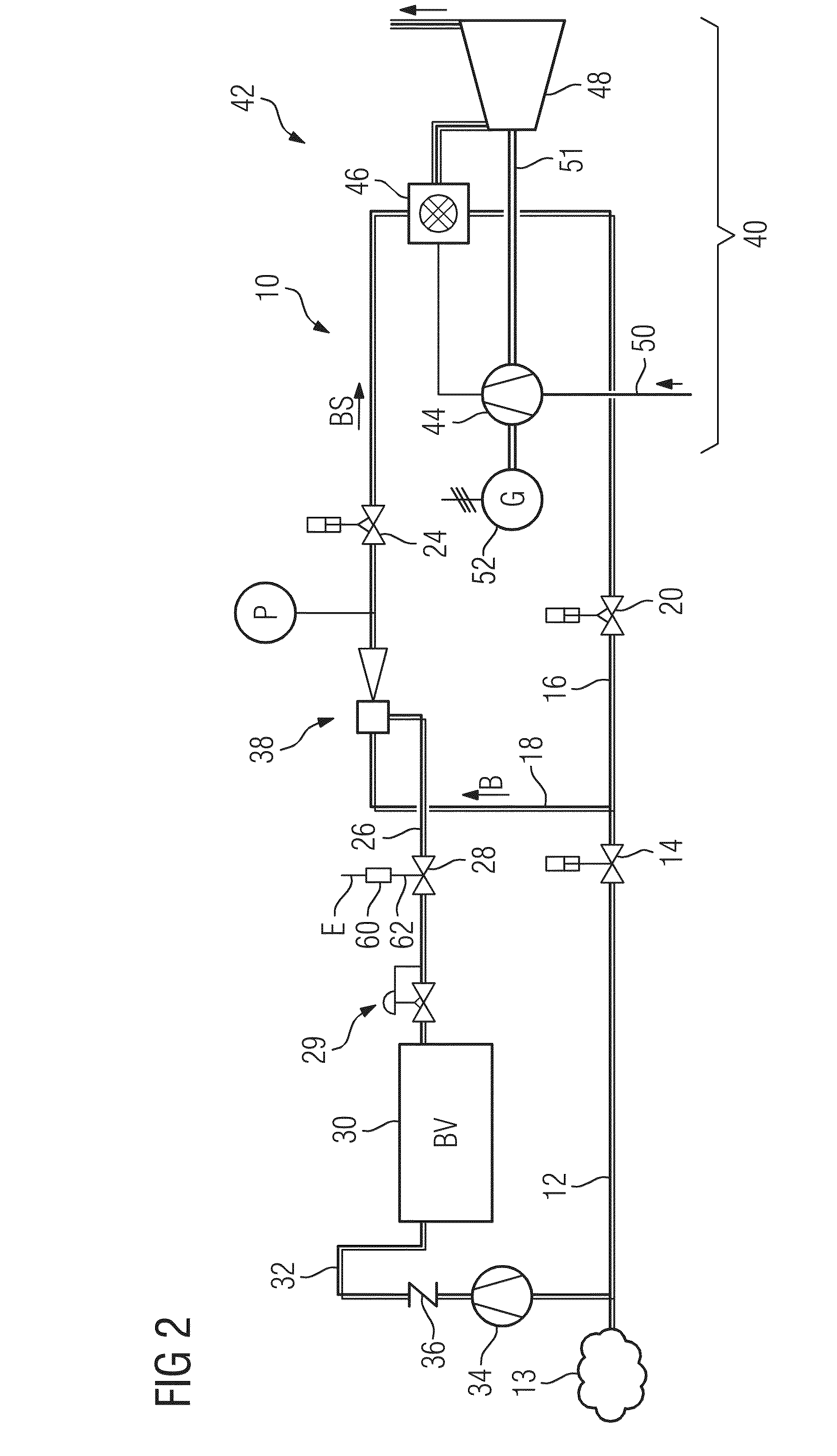
[0031]FIG. 1 shows a power plant 42 having a gas turbine 40. Said gas turbine comprises a compressor 44 of axial type of construction, one or more combustion chambers 46, and a turbine unit 48 which is likewise of axial type of construction. During the operation of the gas turbine 40, ambient air is sucked in by the compressor 44 via an intake line 50 and fed as compressed compressor outlet air into the combustion chamber 46. Both a pilot fuel stream and also a main fuel stream are supplied via one or more burners or stages to the combustion chamber 46 or the combustion chambers 46 and burned, in conjunction with the compressed ambient air, to form a hot gas which expands in the turbine unit 48 at a rotor 51 of the gas turbine 40 while performing work. Said rotor drives a generator 52, which is coupled thereto, for generating electrical energy.

[0032]The gas turbine 40 of the power plant 42 is connected via a fuel supply system 10 to a fuel network 13. The fuel network 13 is capable ...


PUM


Abstract

A method of operating a gas turbine, a device for regulating the starting and / or the operation of a gas turbine and a power plant are provided. The method includes continuously extracting fuel from a fuel network, and combusting, in at least one combustion chamber of a gas turbine, the fuel by adding combustion air. For an increase of a fuel stream supplied to the at least one combustion chamber, a fuel volume is extracted from a fuel store and supplied to the fuel still to be supplied to the at least one combustion chamber.

Description

CROSS REFERENCE TO RELATED APPLICATIONS[0001]This application is the US National Stage of International Application No. PCT / EP2011 / 071243 filed Nov. 29, 2011, and claims benefit thereof, the entire content of which is hereby incorporated by reference. The International Application claims priority to European Application No. 10193135.0 EP filed Nov. 30, 2010, the entire contents of which is hereby incorporated by reference.FIELD OF INVENTION[0002]The invention relates to a method for operating a static or stationary gas turbine, having the steps:[0003]continuous extraction of gaseous fuel from a fuel network and[0004]combustion of the fuel, with the addition of combustion air, in at least one combustion chamber of the gas turbine.[0005]The invention also relates to a device for regulating the operation of a gas turbine. Finally, the invention relates to a power plant comprising a gas turbine having at least one combustion chamber and one compressor, wherein to the combustion chamber ...

Claims


Application Information

Patent Timeline
Patent Type & Authority Applications(United States)
IPC IPC(8): F02C7/22
CPCF02C9/28F02C9/38F02C9/46F05D2270/091F05D2270/092F05D2270/021F02C7/22
Inventor DEUKER, EBERHARDEICKELKAMP, JANKOCK, BORIS FERDINANDKOSTLIN, BERTHOLDMEISL, JURGENNEHLSEN, DENNIS
Owner SIEMENS AG
Why Eureka
Try Eureka