Pin and pawl style bi-directional overrunning clutch

Active Publication Date: 2013-09-26
WARNER ELECTRIC TECH
View PDF7 Cites 10 Cited by
  • Summary
  • Abstract
  • Description
  • Claims
  • Application Information

AI Technical Summary

Benefits of technology

[0008]An improved clutch is provided. In particular, an overrunning clutch is provided that enables improved contro

Problems solved by technology

These actuation methods increase the operating complexity and cost of the clutch.
This sliding motion results in friction that increases temperatures within the clutch and wear on the surfaces of the clutch.
The wear generates metal particles that abrade the surfaces of the clutch and cause even greater wear.
Second, to achieve sufficient centrifugal force, the angular speed and mass of the shoes must be relatively high.
Formation of the grooves requires specialized manufacturing and heat treatment to increase material hardness thereby increasing manufacturing costs and complexity.
The grooves also have sharp corners and edges that act as stress risers and reduce the clutch's strength and durability.

Method used


Image

  • Pin and pawl style bi-directional overrunning clutch
  • Pin and pawl style bi-directional overrunning clutch
  • Pin and pawl style bi-directional overrunning clutch

Examples


Embodiment Construction

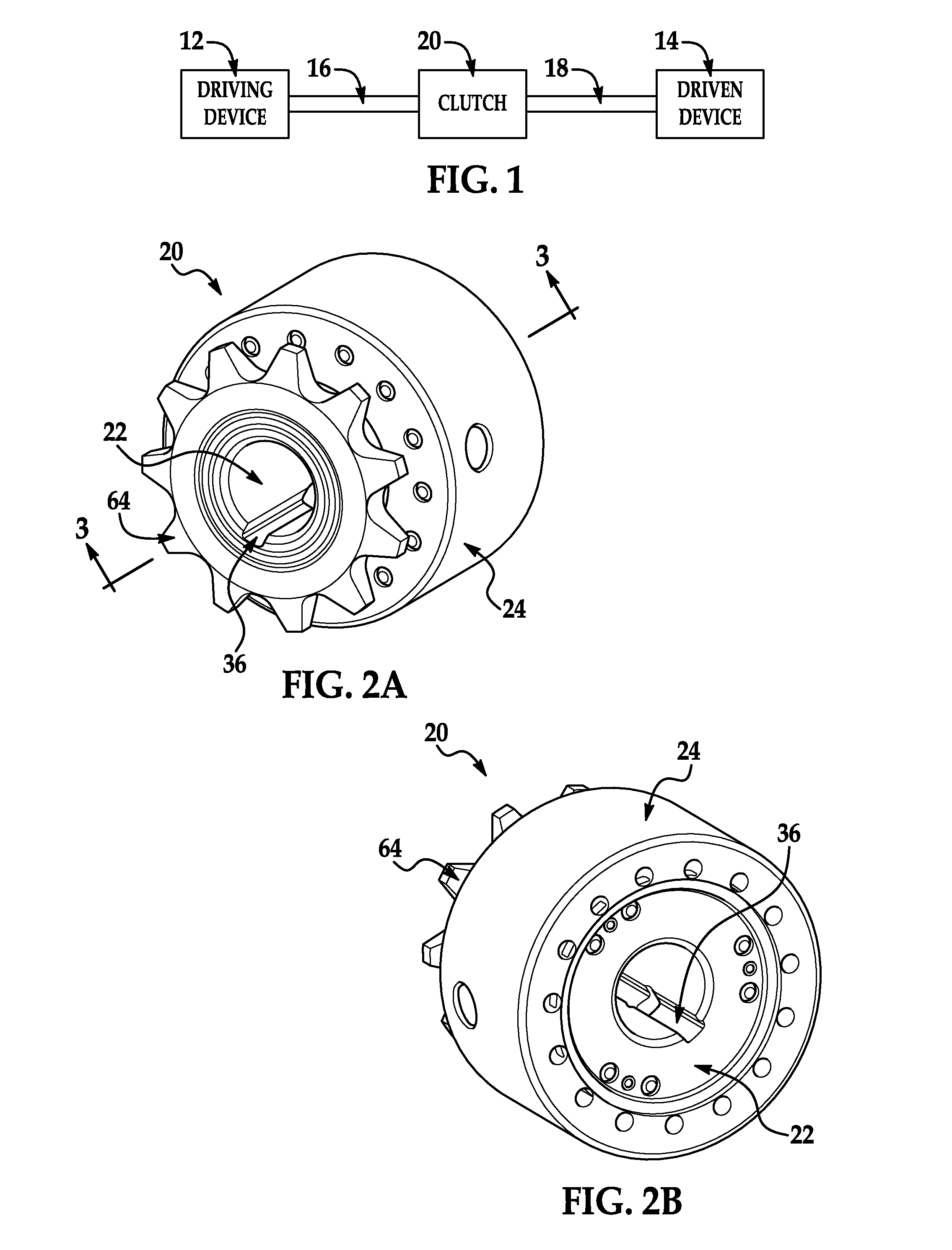
[0024]Referring now to the drawings wherein like reference numerals are used to identify identical components in the various views, FIG. 1 illustrates a power generation and transmission system 10. System 10 includes a driving device 12 for generating power used to drive a driven device 14. The driving device 12 may comprise a conventional motor including, for example, an electric motor, hydraulic motor or pneumatic motor. Device 12 may further include a conventional gear box or speed reducer (which may be combined with the motor to form a conventional gear motor) to control the output speed and torque delivered to driven device 14. Device 12 may output rotational torque through an output member 16 such as a shaft or another rotating body such as a gear, pulley or sprocket. Driven device 14 may comprise, for example, a conveyor or a reel on which is mounted a hose, an electric cable or a steel cable. It should be understood, that the form of device 14 will depend on the application ...


PUM


Abstract

An overrunning clutch is provided having inner and outer members disposed about a rotational axis with the outer member radially outward of the inner member. The clutch further includes a plurality of pins projecting from one of a radially inner surface of the outer member and a radially outer surface of the inner member. The clutch further includes one or more pawls coupled to one of the inner and outer members. Each of the pawls is movable between an engagement position wherein the pawl is engaged with one of the pins to transmit torque between the inner and outer members and a disengagement position wherein the pawl is disengaged from the pin to permit relative rotation of the inner and outer members. In one embodiment, different pawls assume their respective engagement position depending on the rotational direction of the one member.

Description

BACKGROUND OF THE INVENTION[0001]a. Field of the Invention[0002]This invention relates to an overrunning clutch. In particular, the instant invention relates to a clutch having a structure that enables improved control of clutch engagement, and smaller, more evenly distributed loads on clutch engagement surfaces.[0003]b. Background Art[0004]Clutches are used in many applications to selectively engage and disengage a driving device such as a motor with a driven device (e.g. a conveyor or a reel for a hose or cable) in order to transfer torque from the driving device to the driven device. In many clutches, engagement and / or disengagement occurs through electro-magnetic or fluid actuation or even manually by the user. These actuation methods increase the operating complexity and cost of the clutch. To address this drawback, in other clutches engagement and / or disengagement occurs mechanically through, for example, the use of springs and / or in response to external forces operating on th...

Claims


Application Information

Patent Timeline
IPC IPC(8): F16D41/16F16D41/12
CPCF16D41/16
Inventor RUBINO, MARCOS T.
Owner WARNER ELECTRIC TECH
Why Eureka
Try Eureka