Light source

Active Publication Date: 2013-09-26
APPOTRONICS CORP LTD
View PDF2 Cites 73 Cited by
  • Summary
  • Abstract
  • Description
  • Claims
  • Application Information

AI Technical Summary

Benefits of technology

[0012]The light source devices according to embodiments of the present invention have the advantages of a simple optical design. Their optical components are easy to manufacture, and the devices are practical. Mo

Problems solved by technology

Traditional light sources, such as fluorescent light, incandescent light, ultra-high performance lamps and xenon lights, cannot achieve high efficiency and long life.
Using green light as an example, current green LED or green laser cannot achieve high efficiency and are expensive.
A problem with this is that when the converted light passes through the phosphor layer, a part of it is scattered back to the LED chip; because the LED chip absorbs a part of this light, the absorbed part of the converted light will not be output by the light source, resulting in a loss.
Further, the heat generated by the LED chip and the heat generated by the wavelength conversion material interfere with each ot

Method used


Image

  • Light source
  • Light source
  • Light source

Examples


Embodiment Construction

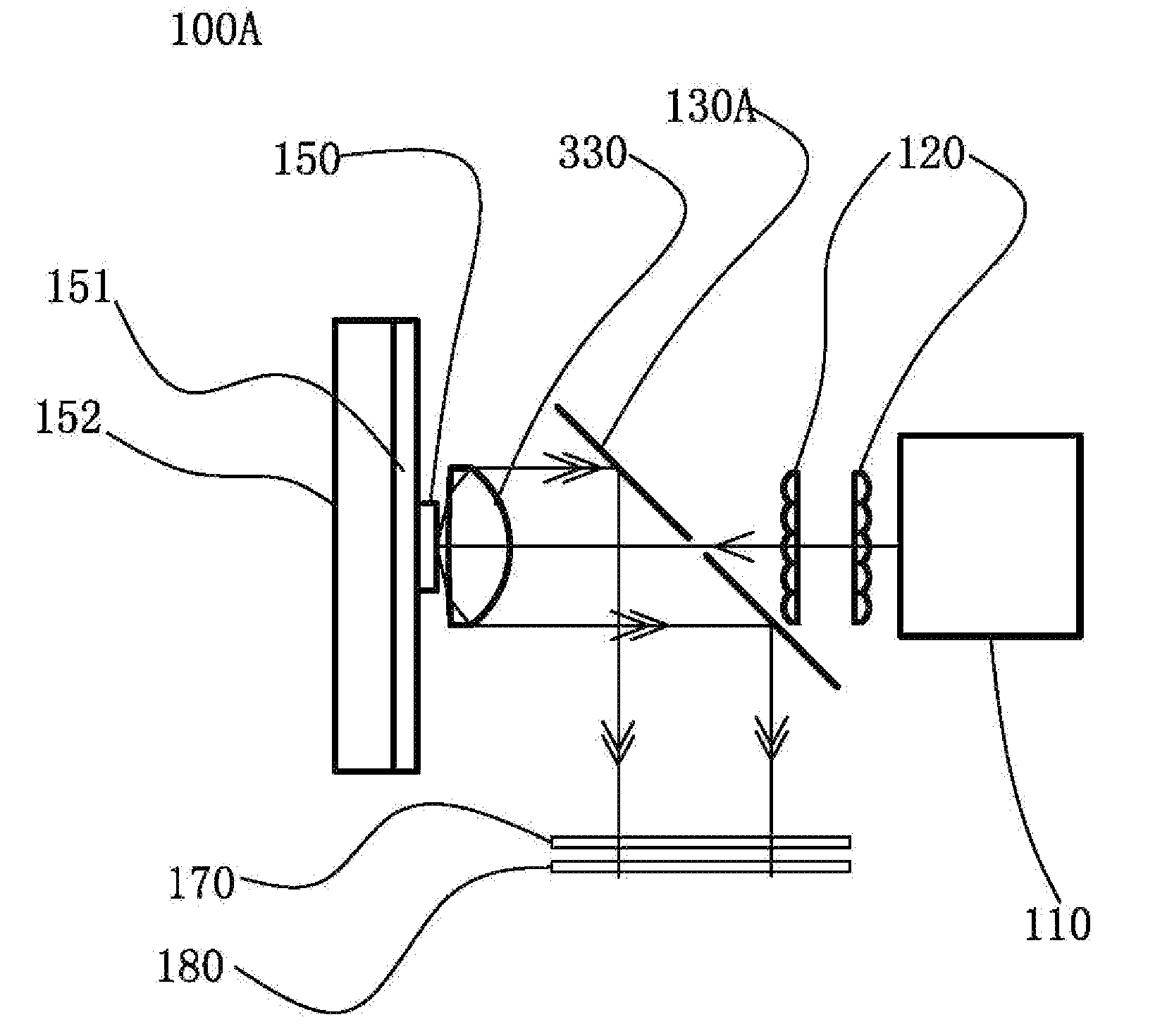
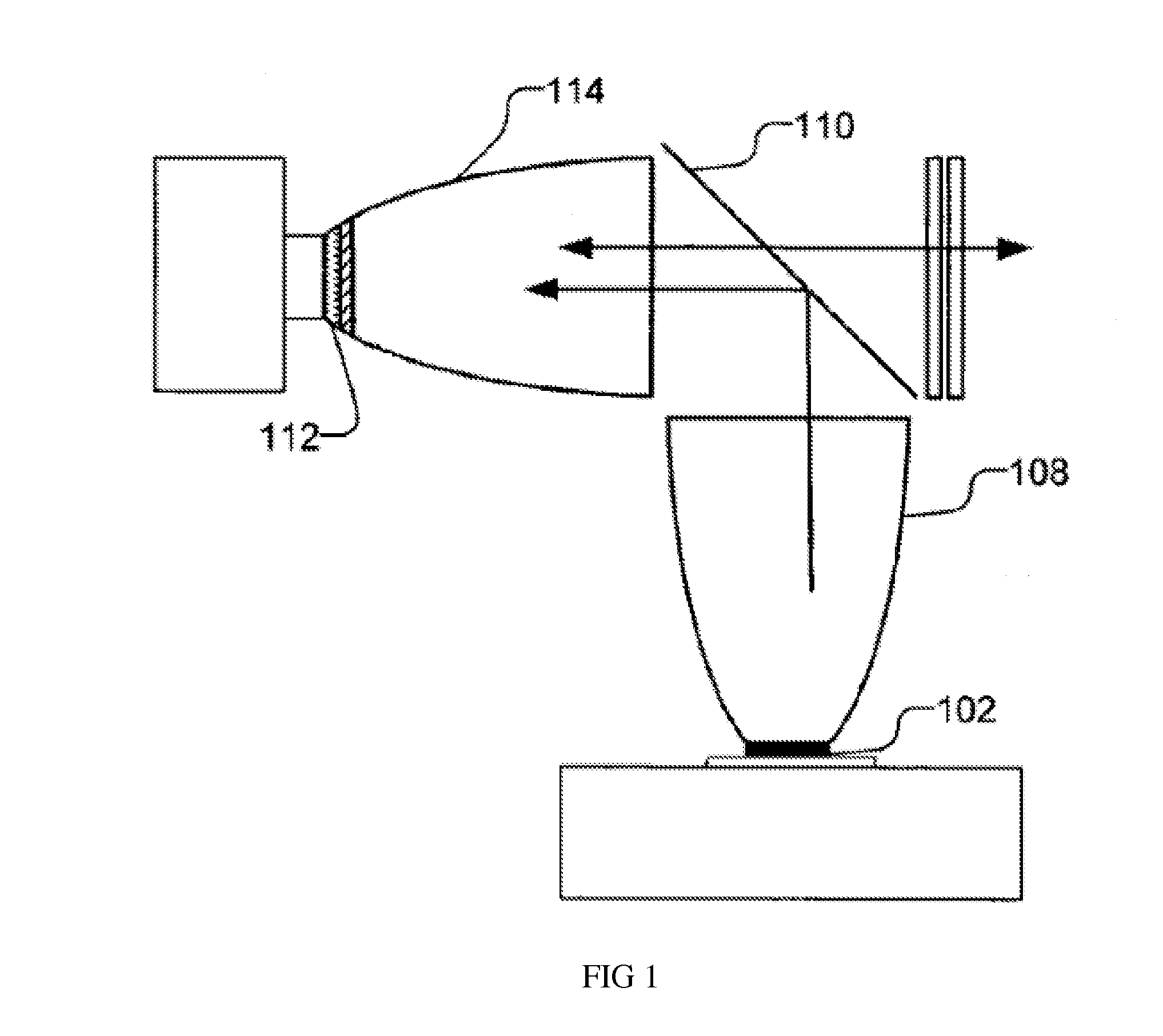
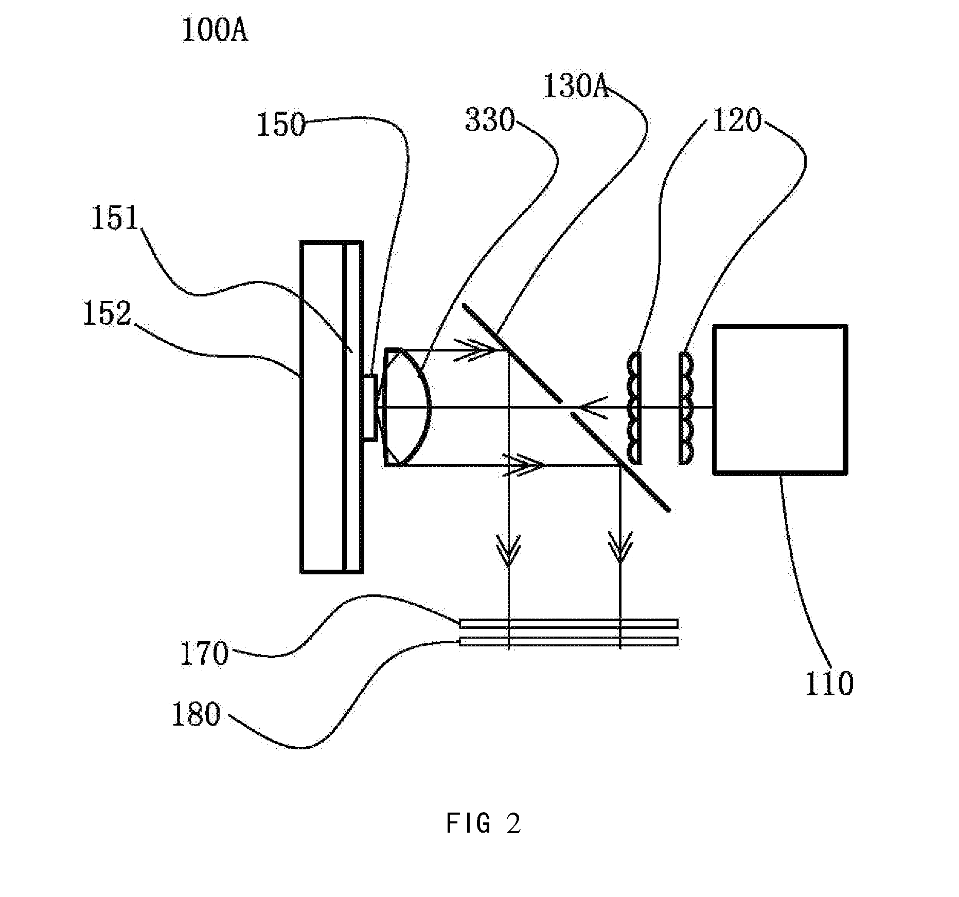
[0027]Embodiments of the present invention will be described below with reference to the drawings.

[0028]A design premise of embodiments of the present invention, which separates optical paths of the excitation light and converted light, is that the light source device includes a wavelength conversion material and an excitation light source providing an excitation light. A light collecting device is used to collect and direct the converted light from the wavelength conversion material, as well as the un-absorbed portion of the excitation light, as the output light of the light source device. The etendue of the excitation light source is less than or equal to ¼ of the etendue of the light collecting device. A light introducing device having an etendue similar to the etendue of the excitation light is provided; it utilizes the optical path of the converted light collected by the light collecting device to introduce the excitation light from the excitation light source onto the waveleng...


PUM


Abstract

A light source comprising an excitation light source (110) for providing excitation light, and an optical wavelength conversion member disposed at a distance from the excitation light source. The optical wavelength conversion member comprises an optical wavelength conversion material (150) for converting the excitation light into stimulated light. The light source also comprises an optical-guiding member that allows the excitation light to be incident on the optical wavelength conversion material, and an optical-collecting member (130A) for collecting stimulated light originating from the optical wavelength conversion material. To separate the paths of the stimulated light and the excitation light, the etendue of the optical-guiding member is less than or equal to ¼ of the etendue of the optical-collecting member. This allows the optical-guiding member to draw in the excitation light while preventing the excessive escape of the stimulated light through the optical-guiding member. The advantages of the light source are that it can separate the paths of the excitation light and the stimulated light, the light path is simple, and the optical members are easy to manufacture.

Description

BACKGROUND OF THE INVENTION[0001]1. Field of the Invention[0002]This invention relates to light sources, and in particular, it relates to light sources based on wavelength conversion.[0003]2. Description of the Related Art[0004]Traditional light sources, such as fluorescent light, incandescent light, ultra-high performance lamps and xenon lights, cannot achieve high efficiency and long life. With the development of solid state light sources, light emitting diodes (LED) and semiconductor laser are gaining wide use in illumination device and display device markets.[0005]There are typically two ways of generating a white light or a color light: one method directly uses color light sources such as red, green and blue LEDs to provide color lights, or mixes these color lights to generate a white light; the other method is based on wavelength conversion, which uses an excitation light to excite wavelength conversion materials to generate color lights, and further generates a white light by...

Claims


Application Information

Patent Timeline
IPC IPC(8): F21V9/16F21V13/08F21V9/40
CPCF21V9/08F21V9/16G03B21/204F21Y2101/02F21V13/08F21Y2115/10G02B19/0028G02B19/0047G02B26/008G02F2/006F21S10/007F21K9/64F21Y2115/00G03B21/14G03B21/2066G03B21/28H04N9/3114H04N9/3117H04N9/315H04N9/3155H04N2209/043
Inventor HU, FEILI, YIYANG, YI
Owner APPOTRONICS CORP LTD
Why Eureka
Try Eureka