Method and a Device for Relaying in a Communications Network

a communication network and relay technology, applied in the field of digital communications and network coding, can solve the problems of reducing the reception rate at the destination, affecting the reception rate of the destination, and propagating errors to the destination

Active Publication Date: 2013-09-26
FRANCE TELECOM SA
View PDF14 Cites 17 Cited by
  • Summary
  • Abstract
  • Description
  • Claims
  • Application Information

AI Technical Summary

Benefits of technology

[0039]As mentioned above, this sum makes it possible to recover a message providing all of the other messages are known. Knowledge of the modulo-2 sum and of the other messages makes it possible to recover one message and thus to recover all of the messages in the presence of only one link being interrupted.
[0040]In an implementation, the detection / decoding step is iterative. An iterative method is the most effective (in terms of performance and complexity) for practically performing joint detection at the destination, while making use of the signals received and transmitted from the sources together with the representative signal received and transmitted from the relay.

Problems solved by technology

This can lead to errors being propagated to the destination.
The technique described in that prior art scientific publication includes at least the following two drawbacks:the relaying function relies on the “joint selective” approach: the relay transmits nothing if one of the two source messages is detected as being erroneous at the relay; andthe “code design” is limited to circumstances in which the sources and the relay use the same coding schemes.
With such coding, the signal transmitted by the relay does not enable the destination to detect the messages transmitted by the sources; the destination must implement joint detection making use simultaneously of the representative signal sent by the relay and the signals received by the destination and coming directly from the sources.
This results in simplification of reception at the destination.

Method used


Image

  • Method and a Device for Relaying in a Communications Network
  • Method and a Device for Relaying in a Communications Network
  • Method and a Device for Relaying in a Communications Network

Examples


Embodiment Construction

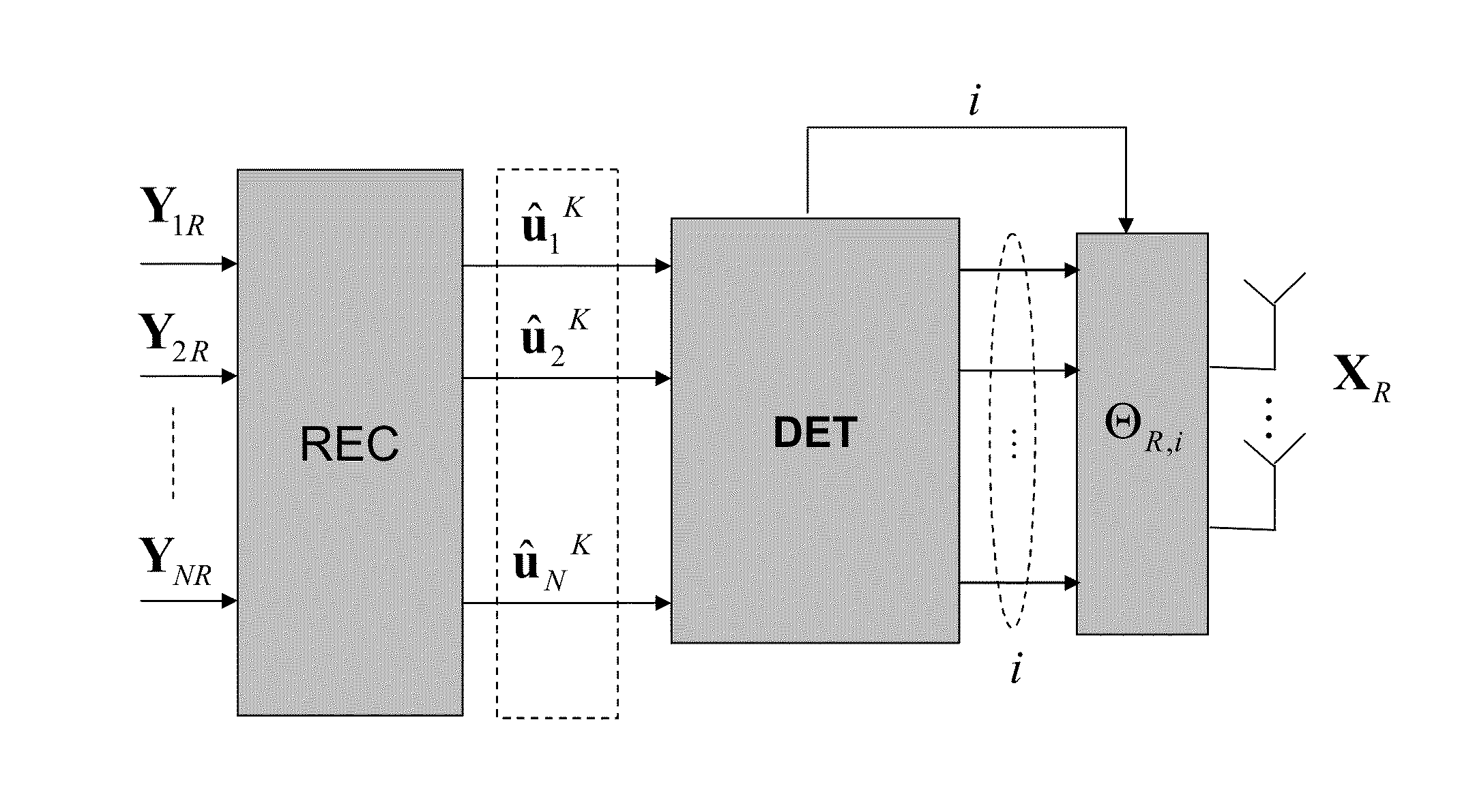
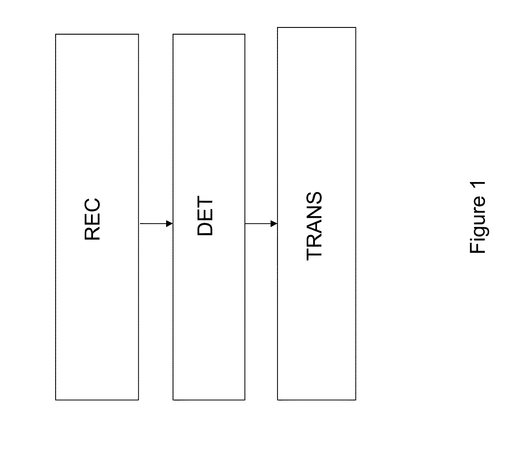
[0063]FIG. 1 shows the method of an embodiment of the present invention in one implementation. The method comprises a reception step (written REC in FIG. 1) in which the relay R receives messages u1, u2, . . . , uN each associated with a respective source, a detection step (written DET in FIG. 1), in which the relay R detects errors in the messages; and a transmission step (written TRANS in FIG. 1) in which the relay (R) transmits a signal to the destination (D), which signal is representative of only those messages for which no error is detected. The representative signal is transmitted by the relay R to the destination D together with a check signal indicating which messages are represented in the representative signal.

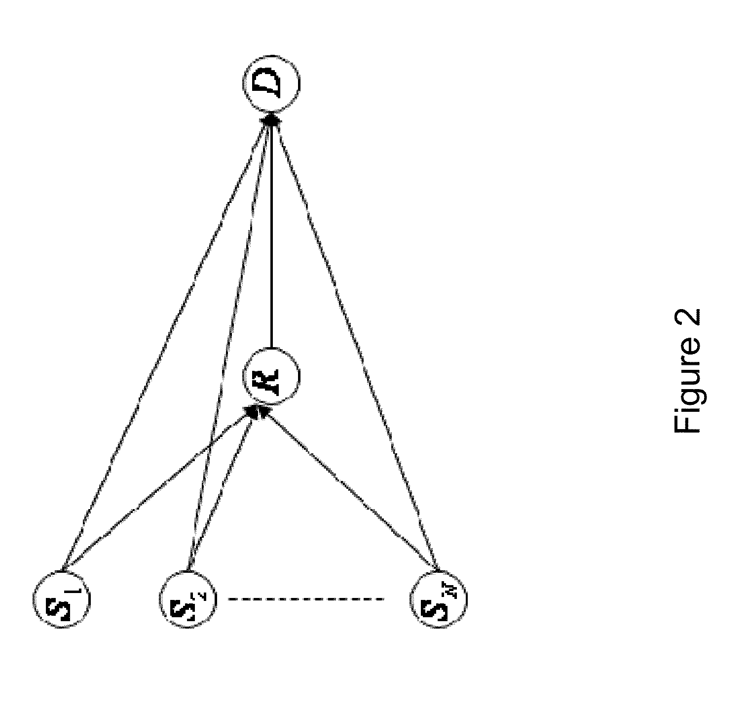
[0064]FIG. 2 is an abstract model of communication between N nodes S1, S2, . . . , SN and the destination D with the help of a relay channel R. The communications system of an embodiment of the invention comprises at least the relay R and the destination D. By way o...


PUM


Abstract

A method and device for selective relaying in a communications network having a plurality of sources, a relay, and a destination. The method includes the following steps: the relay receives messages transmitted respectively by the sources in order to obtain an estimate of the messages; the relay detects errors in the estimated messages; the relay transmits a representative signal to the destination, the signal being representative of only those messages for which no error was detected and resulting from a non-bijective surjective function applied to the messages detected without error, the function including interleaving and encoding; and the representative signal being transmitted by the relay to the destination with a check signal indicating which messages are represented in the representative signal.

Description

CROSS-REFERENCE TO RELATED APPLICATIONS[0001]This Application is a Section 371 National Stage Application of International Application No. PCT / FR2011 / 051893, filed Aug. 9, 2011, which is incorporated by reference in its entirety and published as WO 2012 / 022905 on Feb. 23, 2012, not in English.STATEMENT REGARDING FEDERALLY SPONSORED RESEARCH OR DEVELOPMENT[0002]None.THE NAMES OF PARTIES TO A JOINT RESEARCH AGREEMENT[0003]None.FIELD OF THE DISCLOSURE[0004]The present disclosure relates to a method and to a device for relaying in a communications network.[0005]In general manner, the present disclosure relates to the field of digital communications.[0006]The present disclosure relates more particularly to the problem of network coding, with networks having relays forming a part of that problem. The present disclosure applies to a multi-user network made up of a plurality of sources, a relay, and a destination (using the multiple-access relay channel (MARC) model). In this type of networ...

Claims


Application Information

Patent Timeline
Patent Type & Authority Applications(United States)
IPC IPC(8): H04L1/24
CPCH04B7/15521H04L1/244H04W88/04H04L1/0083H04L1/0061H04L2001/0097H03M13/093
Inventor HATEFI, ATOOSAVISOZ, RAPHAELBERTHET, ANTOINE
Owner FRANCE TELECOM SA
Why Eureka
Try Eureka