Turbine

Active Publication Date: 2013-09-26
MITSUBISHI POWER LTD
View PDF1 Cites 14 Cited by
  • Summary
  • Abstract
  • Description
  • Claims
  • Application Information

AI Technical Summary

Benefits of technology

[0020]According to the configuration, it is possible to reduce the diameter of the separation vortices generated on the circumference surfaces of the step surfaces of the two adjacent stepped parts. Furthermore, since the inclination angle of the inclined surface formed on the stepped part on the downstream side is greater than that of the stepped part on the upstream side, it is possible to strengthen a tendency of reducing the diameter of the separation vortex generated on the circumference surface of the stepped part on the downstream side so as to be smaller than that of the stepped part on the upstream side. Therefore, it

Problems solved by technology

However, leakage steam passing to the downstream side through the clearance between the tip portion of the turbine blade and the casing does not impart torque to the turbine blade.
Furthermore, in leakage st

Method used


Image

  • Turbine
  • Turbine
  • Turbine

Examples


Example

[0030]Hereinafter, a first embodiment of the present invention will be described referring to FIGS. 1 to 4C.

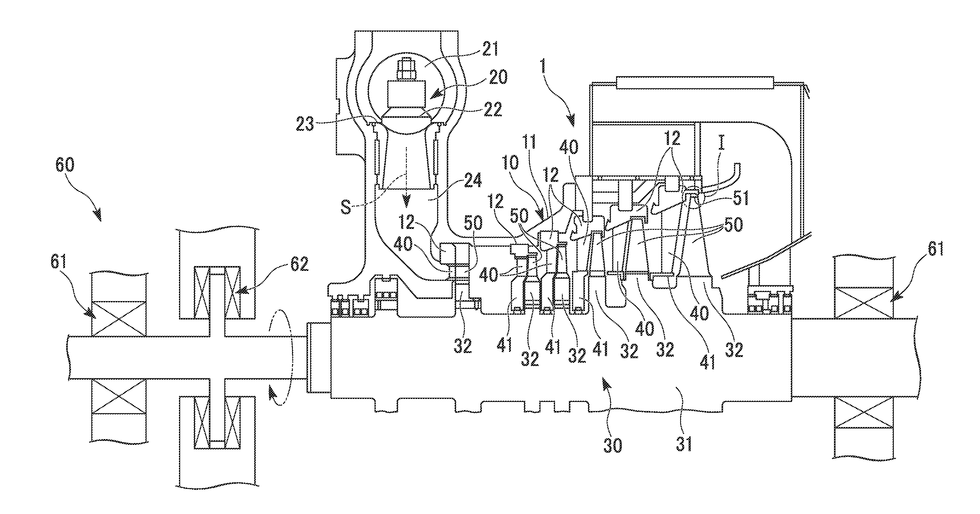
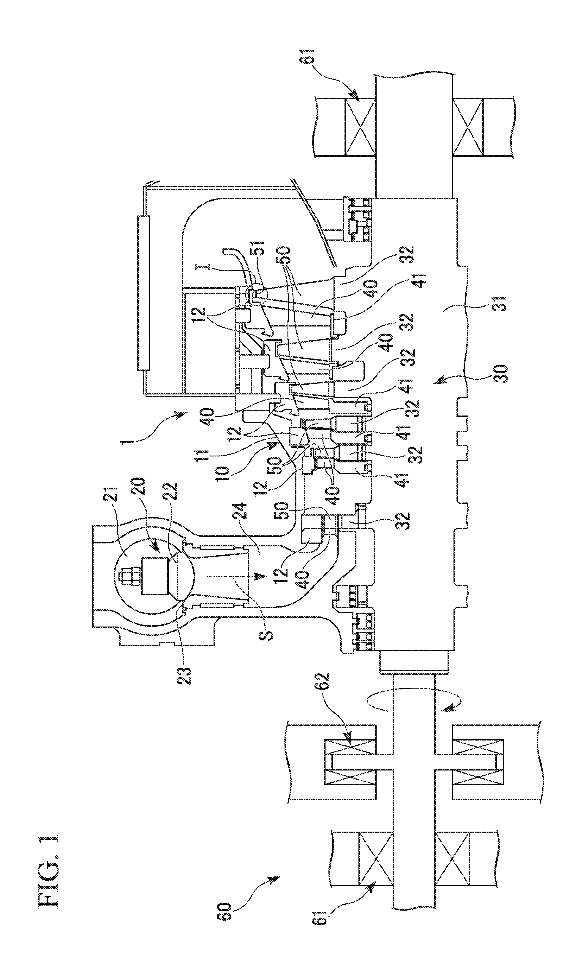
[0031]As shown in FIG. 1, a steam turbine 1 according to the embodiment is schematically constituted to include a casing (structural member) 10, a regulating valve 20 to regulate the amount and pressure of steam (fluid) S flowing into the casing 10, a shaft body (rotor) 30 which is provided inside the casing 10 so as to rotate freely and transmits power to a machine such as a generator (not shown), turbine vanes 40 held in the casing 10, turbine blades (blades) 50 provided in the shaft body 30, and a bearing portion 60 which supports the shaft body 30 so as to be axially rotatable.

[0032]The casing 10 is formed such that an inner space thereof is sealed hermetically. The casing 10 includes a main body portion 11 which forms a flow channel of the steam S and a ring-shaped diaphragm outer ring 12 which is securely fixed on an inner wall surface of the main body portion 11.

[0033]A...

Example

Second Embodiment

[0079]Next, the second embodiment of the present invention will be described referring to FIGS. 5 and 6.

[0080]Upon comparison with the steam turbine 1 of the first embodiment, the second embodiment has a difference in that only the shape of each stepped part 52 is different from that of the first embodiment, and other configurations are the same as those in the first embodiment. In the second embodiment, the same reference numerals and signs are given to the same constituent elements as those of the first element, and the description thereof will be omitted.

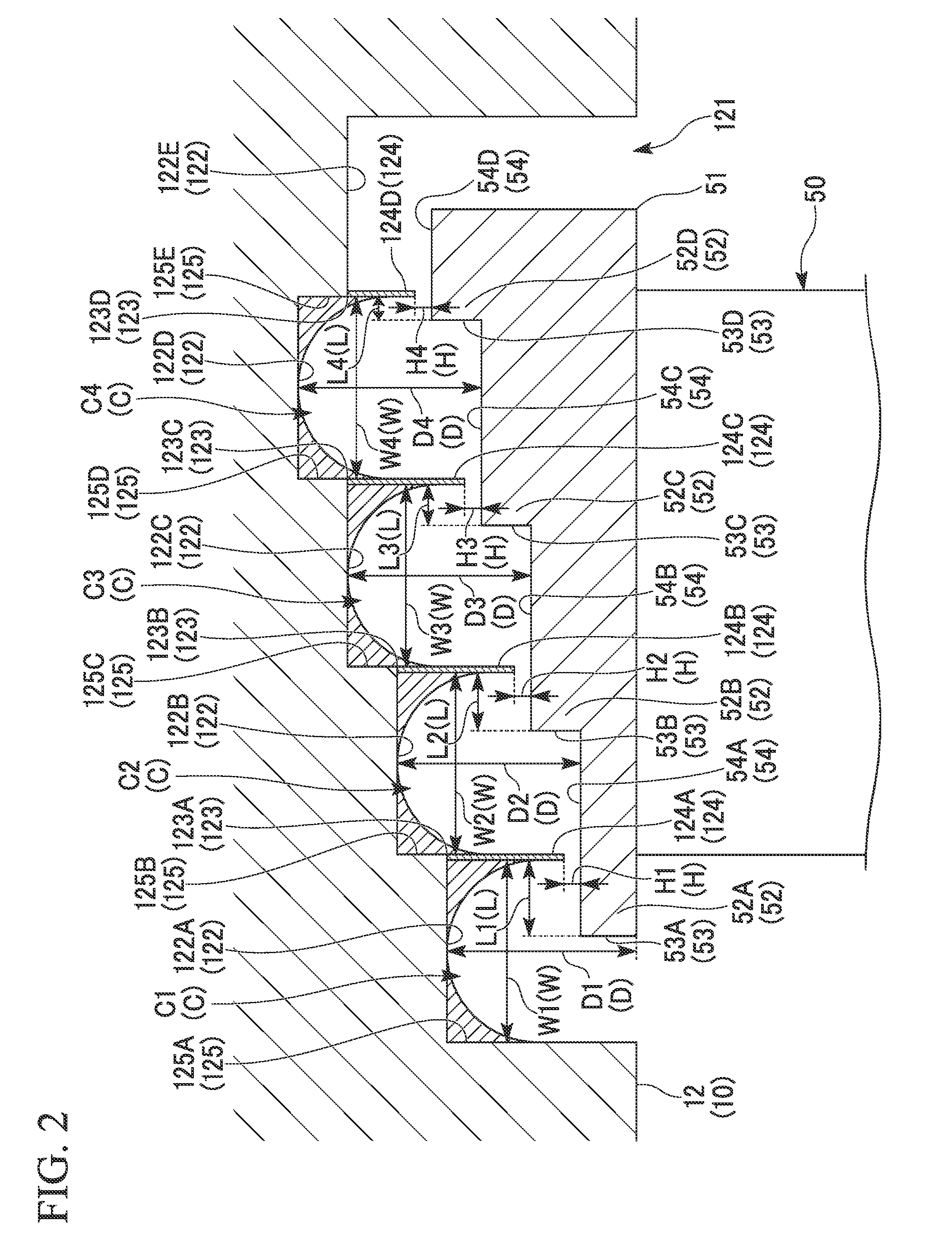
[0081]As shown in FIG. 5, inclined surfaces 56 (56A to 56D) inclined from the upstream side to the downstream side are respectively formed on the step surfaces 53 (53A to 53D) of the stepped parts 52 (52A to 52D) so as to be continuous with each of the outer circumference surfaces 54 (54A to 54D) of the same stepped parts 52.

[0082]Furthermore, in the four inclined surfaces 56A to 56D, inclination angles θ1 to θ4 ...


PUM


Abstract

A plurality of stepped parts which have step surfaces facing an upstream side in a rotating axial direction of a structural member are provided in a tip portion of a blade, and seal fins which extend toward a circumference surface of each of the stepped parts and form small clearances between the seal fin and the circumference surface corresponding to the each of the stepped parts is provided in the structural member. Also, lengths from the small clearance to the step surface on the upstream side along the rotating axial direction of the structural member are set such that one of the stepped parts on the downstream side is smaller than the other one of the stepped parts on the upstream side.

Description

TECHNICAL FIELD[0001]The present invention relates to a turbine, for example, that is used in power plants, chemical plants, gas plants, iron mills and marine vessels. Priority is claimed on Japanese Patent Application No. 2012-067893 filed Mar. 23, 2012, the content of which is incorporated by reference herein.BACKGROUND ART[0002]As a well-known type of steam turbine, one is known which is provided with a casing, a shaft body (rotor) installed inside the casing so as to be rotatable, a plurality of turbine vanes arranged by being fixed to an inner circumference portion of the casing and a plurality of turbine blades radially installed at the shaft body in the downstream side of the plurality of turbine vanes. Of these steam turbines, an impulse turbine converts pressure energy of steam (fluid) to velocity energy by turbine vanes and also converts the velocity energy to rotational energy (mechanical energy) by turbine blades. Further, in a reaction turbine, pressure energy is conver...

Claims


Application Information

Patent Timeline
IPC IPC(8): F01D5/12
CPCF05D2250/28F01D5/147F01D5/12F05D2240/307F01D11/10F01D5/225
Inventor MATSUMOTO, KAZUYUKIKUWAMURA, YOSHIHIROOYAMA, HIROHARUTANAKA, YOSHINORI
Owner MITSUBISHI POWER LTD
Why Eureka
Try Eureka