Electrical bypass element, in particular for storage cells of an energy storage device

a technology of bypass element and energy storage device, which is applied in the direction of cell components, cell component details, electrochemical generators, etc., can solve the problems of premature triggering, short circuit of storage cell with low impedance, and inability to prevent high power loss, for exampl

Active Publication Date: 2013-09-26
FRAUNHOFER GESELLSCHAFT ZUR FOERDERUNG DER ANGEWANDTEN FORSCHUNG EV
View PDF2 Cites 28 Cited by
  • Summary
  • Abstract
  • Description
  • Claims
  • Application Information

AI Technical Summary

Benefits of technology

[0008]An embodiment of the invention provides an electrical bypass element comprising of two electrical conductors, between which a layer sequence with at least one electrical insulation layer and one or more reactive layer stacks is formed, in which an exothermic reaction can be triggered. The electrical insulation layer in this layer sequence insulates the two electrical conductors electrically with respect to one another. The one or more reactive layer stacks and the at least one insulation layer are matched to one another or designed or dimensioned such that the insulation layer disintegrates as a result of the thermal energy released by the reactive layer stack(s) during the exothermic reaction and an electrical connection is produced between the electrical conductors. The disintegration of the insulation layer is understood here to mean that the insulation layer is no longer present once the exothermic reaction has taken place or is at least degraded to such an extent that it no longer has an electrically insulating effect between the two electrical conductors. The insulation layer may burn or evaporate for example as a result of the released thermal energy. The insulation layer may also merely melt as a result of the released thermal energy and may either be displaced from the region between the electrical conductors due to an applied mechanical pressure or may mix with an electrically conductive material of an adjacent layer in the layer sequence, for example an additional layer made of a solder material.

Problems solved by technology

When a destroyed storage cell fails with high impedance, the high charging current flows through the two semiconductor components, which break down due to the resultant sharp increase in temperature and thus irreversibly short circuit the storage cell with low impedance.
Premature triggering, for example to prevent high power losses, is not possible.

Method used


Image

  • Electrical bypass element, in particular for storage cells of an energy storage device
  • Electrical bypass element, in particular for storage cells of an energy storage device
  • Electrical bypass element, in particular for storage cells of an energy storage device

Examples


Embodiment Construction

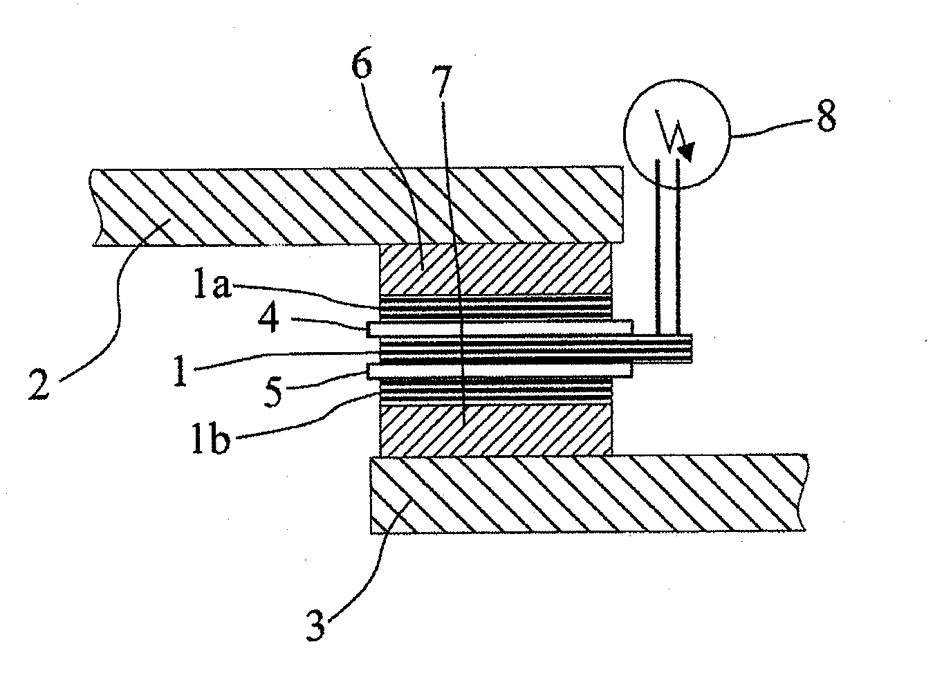
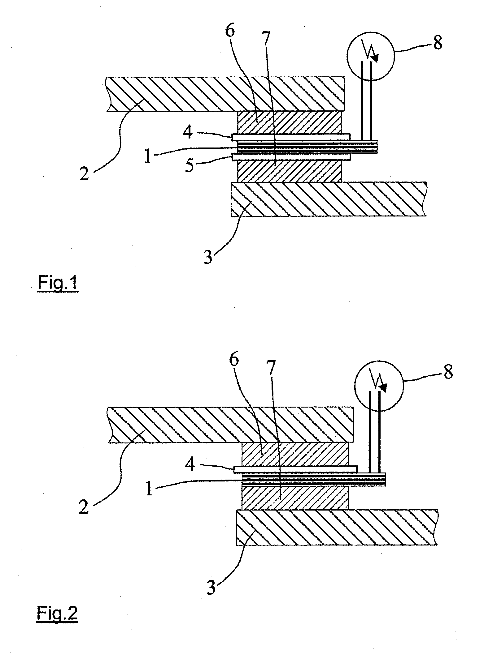
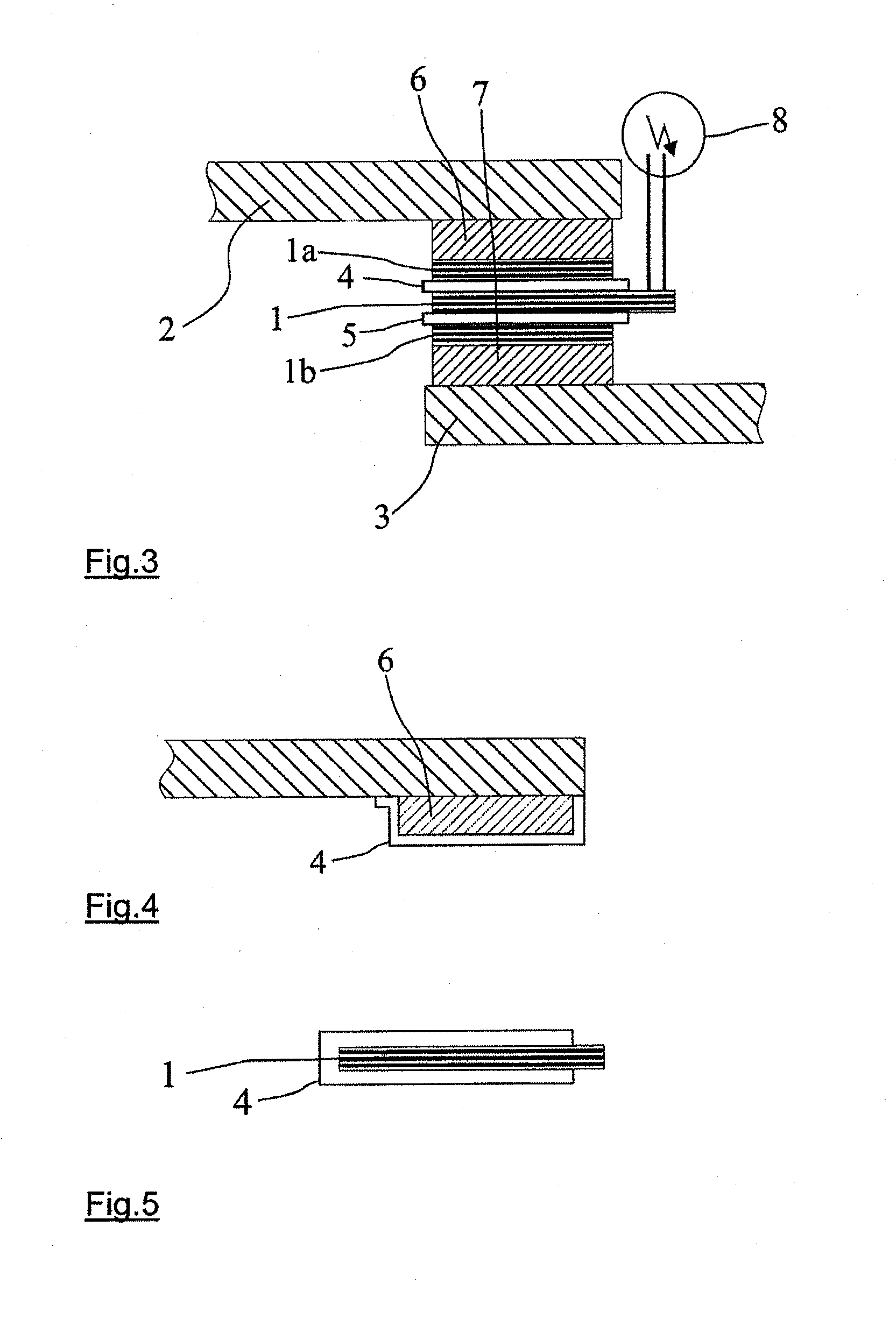
[0029]Different possible embodiments of the proposed active bypass element will be illustrated schematically hereinafter in a cross-sectional view. The individual exemplary embodiments differ in terms of the composition of the layer sequence between the two busbars or busbar tracks 2, 3, which represent the two electrical conductors of the proposed bypass element in these examples. Of course, these electrical conductors may also be formed in another way. The two busbar tracks 2, 3, of each of which only a portion is illustrated in the figures, are connected to the two poles of the accumulator storage, cell to be bypassed by said conductors in the event of a failure.

[0030]For high-impedance insulation of the two busbars or busbar tracks, at least one electrical insulation layer 4, 5 is located between the busbar tracks, a portion of which is coated with a solderable layer 6, 7. In the example in FIG. 1, two electrical insulation layers 4, 5 of this type are arranged on either side of...


PUM

PropertyMeasurementUnit
thicknessaaaaaaaaaa
thicknessesaaaaaaaaaa
total thicknessaaaaaaaaaa

Abstract

An electrical bypass element, suitable for bypassing defective storage cells in energy storage devices includes two electrical conductors between which is formed a layer sequence with at least one electrical insulation layer and one or more reactive layer stacks, in which an exothermic reaction can be triggered. The reactive layer stacks and the insulation layer are matched to one another such that the insulation layer disintegrates as a result of the thermal energy released during the exothermic reaction and an electrical connection is produced between the electrical conductors. The electrical bypass element can be actively triggered even before the ultimate failure of a storage cell so that higher power losses in the energy storage device can be avoided.

Description

CROSS-REFERENCE TO RELATED APPLICATION[0001]This application claims the priority of German Patent Application No. 10 2012 005 979.0, filed on Mar. 23, 2012, which is incorporated herein by reference in its entirety.TECHNICAL FIELD[0002]The present invention relates to an electrical bypass element, which is suitable in particular for bypassing defective storage cells of an energy storage device. The invention also relates to an energy storage device having a plurality of storage cells connected in series, in which an electrical bypass element is connected in parallel to each of the storage cells.[0003]Electrical energy storage devices are key components for hybrid vehicles, fuel cell vehicles and electric vehicles. In particular, modern high-power energy storage devices, which consist of lithium-ion accumulator cells connected in series and in parallel, place very high demands in terms of safety and reliability on the electrical and thermal operating conditions of each individual acc...

Claims


Application Information

Patent Timeline
Patent Type & Authority Applications(United States)
IPC IPC(8): H01M2/34H02H7/16H01M50/51H01M50/574H01M50/588H01M50/593
CPCH01M10/4207H01M10/482Y02T10/7022H02H7/16H01G11/18H01M2/34Y02T10/70Y02E60/10H01M50/588H01M50/593H01M50/51H01M50/574
Inventor VOM DORP, JOACHIMERLBACHER, TOBIASFREY, LOTHAR
Owner FRAUNHOFER GESELLSCHAFT ZUR FOERDERUNG DER ANGEWANDTEN FORSCHUNG EV
Why Eureka
Try Eureka