System and method for controllijng autonomous platform using wire

a technology of autonomous platform and wire, which is applied in the direction of instruments, distance measurement, vessel construction, etc., can solve the problems of increasing the difficulty of maintaining the position and posture of the autonomous platform, and increasing the size of the hull block

Inactive Publication Date: 2013-09-26
SAMSUNG HEAVY IND CO LTD
View PDF4 Cites 9 Cited by
  • Summary
  • Abstract
  • Description
  • Claims
  • Application Information

AI Technical Summary

Benefits of technology

[0007]An embodiment of the present invention provides a system and method for controlling an autonomous platform using a wire that can prevent the wire connected to the autonomous platform from sagging.
[0009]An embodiment of the present invention provides a system and method for controlling an autonomous platform using a wire that can accurately determine a length of the wire fixed to the autonomous platform and a block.
[0010]An embodiment of the present invention provides a system and method for controlling an autonomous platform using a wire that can determine an accurate position and posture of the autonomous platform inside the block by use of the tension acting on the wire.Technical Solution

Problems solved by technology

As vessels become increasingly bigger, blocks that form the hull are also increasingly getting bigger.
However, in the case that the autonomous platform using a wire is under a load, the wire becomes stretched due to the weight of the autonomous platform, making the wire to sag.
If the autonomous platform is disturbed while the wire is sagged, it becomes difficult to maintain the position and posture of the autonomous platform.
Moreover, since the autonomous platform itself has its own weight while a load is applied, the wire gets stretched, and thus it is not easy to move the autonomous platform to a desired position and posture, thereby occurring errors when the welding, painting and inspection are performed.

Method used


Image

  • System and method for controllijng autonomous platform using wire
  • System and method for controllijng autonomous platform using wire
  • System and method for controllijng autonomous platform using wire

Examples


Embodiment Construction

[0053]Hereinafter, a system and method for controlling an autonomous platform using a wire in accordance with an embodiment will be described with reference to the accompanying drawings. In describing the embodiment with reference to the accompanying drawings, any identical or similar elements will be given same reference numerals, and the description thereof will not be redundantly provided.

[0054]Hereinafter, a system for controlling an autonomous platform using a wire in accordance with an embodiment of the present invention will be described with reference to FIG. 1 and FIG. 2.

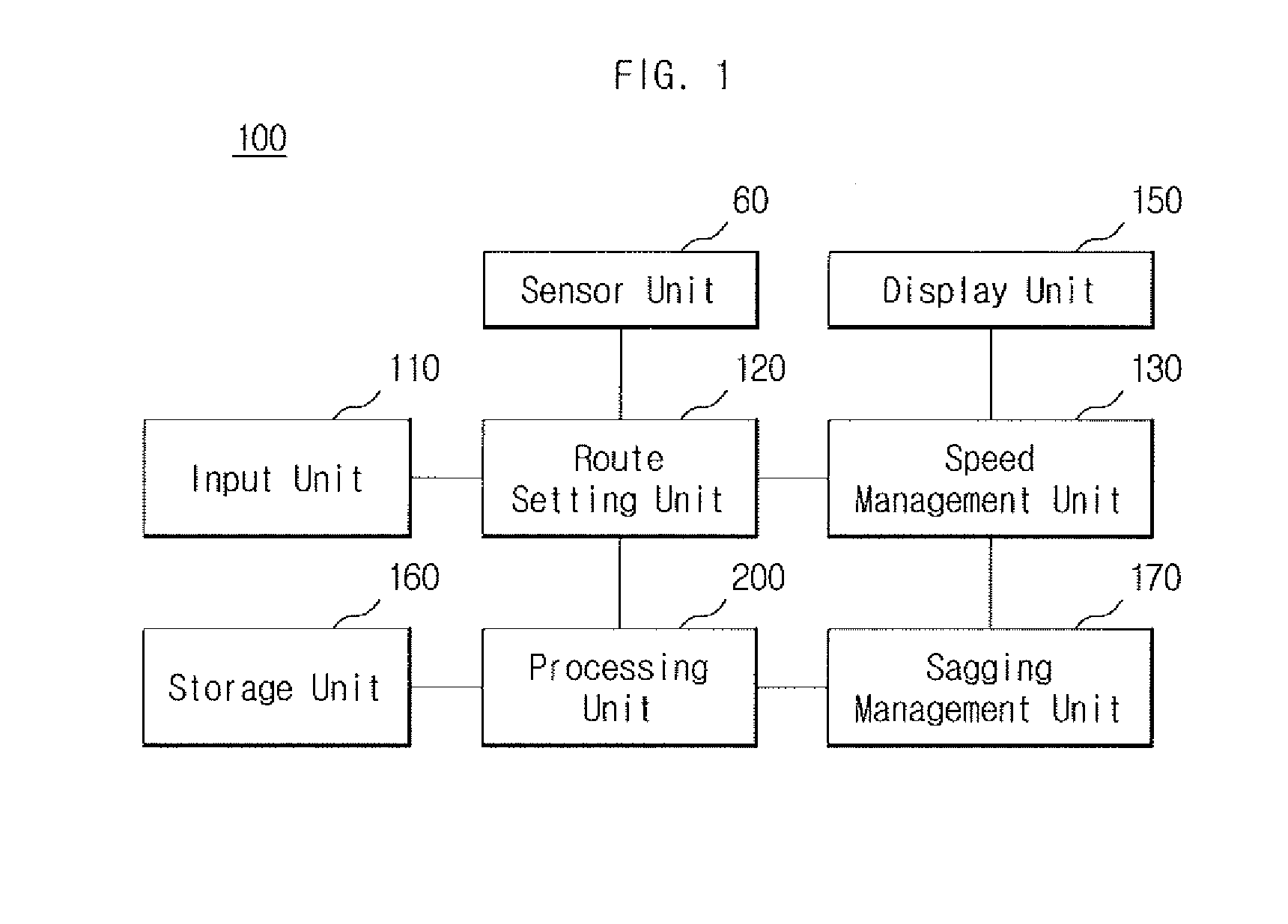
[0055]FIG. 1 is a block diagram illustrating a system for controlling an autonomous platform using a wire in accordance with an embodiment of the present invention.

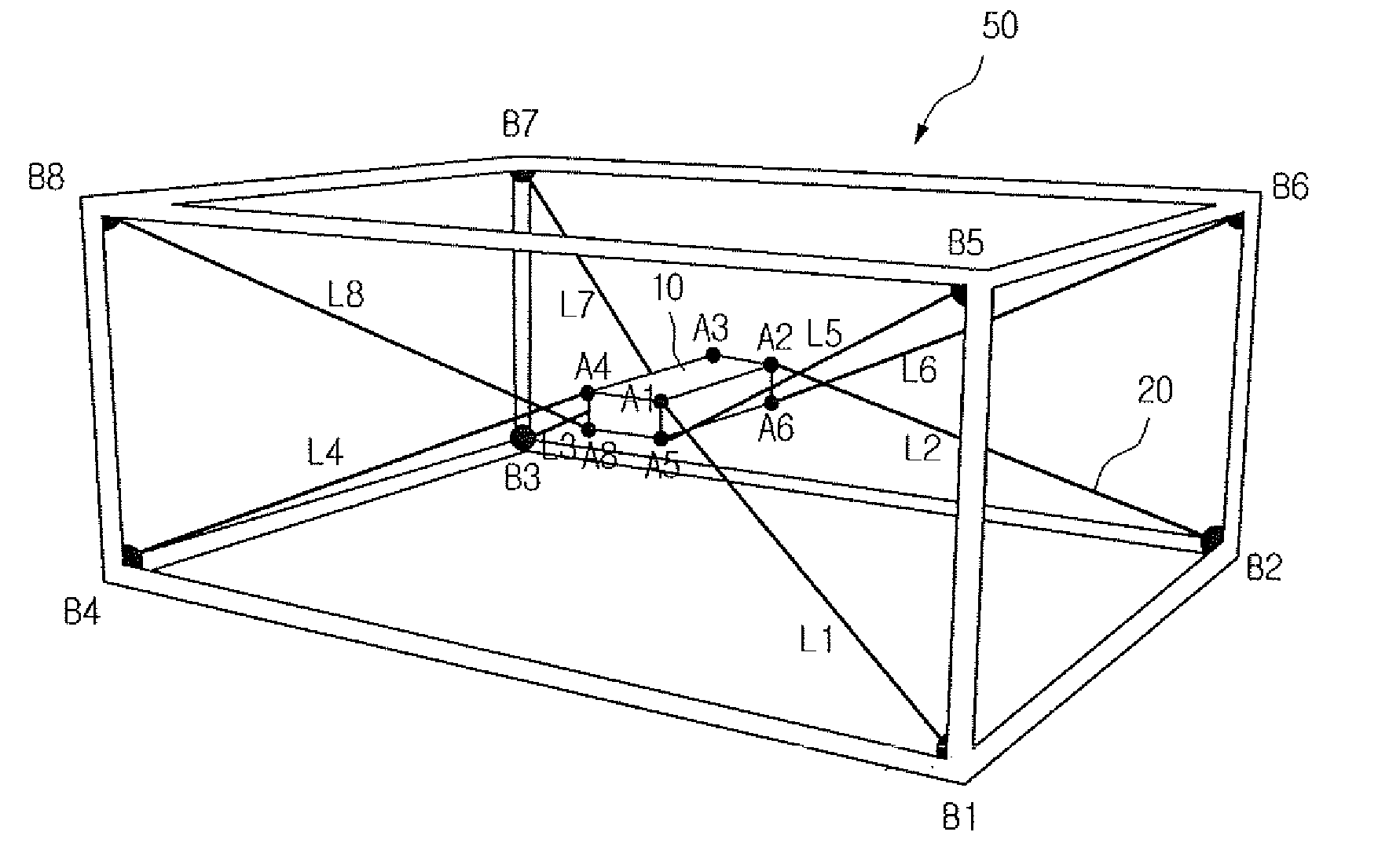
[0056]Referring to FIG. 1, a system for controlling an autonomous platform using a wire 100 (referred to as “autonomous platform control system” hereinafter) uses the wire to move the autonomous platform within a block. Here, the autonomous platf...


PUM


Abstract

Disclosed are a system and method for controlling an autonomous platform using a wire. According to one embodiment of the present invention, an autonomous platform control system for controlling an autonomous platform connected to a wire comprises: a route setting unit which generates movement control information of the autonomous platform using final position information and first position information; a speed management unit which moves the autonomous platform by controlling the speed of the autonomous platform using the movement control information; a processing unit which generates current position information by setting the position and posture of the autonomous platform using a measurement value of a rotation angle of the wire with respect to the moved autonomous platform, and generates wire operation length information by setting the length of the wire using the current position information; and a sagging management unit which determines the sagging of the wire using measurement information on a wire tension acting on the wire, and adjusts the wire using the measurement information on the wire tension when the wire sags.

Description

TECHNICAL FIELD[0001]The present invention relates to a system for controlling an autonomous platform, more specifically to a system and method for controlling an autonomous platform using a wire.BACKGROUND ART[0002]As vessels become increasingly bigger, blocks that form the hull are also increasingly getting bigger. Generally, the hull of a large vessel is constructed by manufacturing the blocks, which constitute portions of the hull, and then assembling the blocks. In other words, after rust or foreign substances on surfaces of raw materials are blasted off and the raw materials are painted for prevention of corrosion, the raw materials are, for example, welded together to build the blocks, and the blocks are assembled with one another to complete the hull.[0003]These blocks need to be welded, blasted and painted inside thereof. Accordingly, various tasks, such as collecting the grits used for blasting, drying / inspecting / measuring paint film after painting, etc., are also performe...

Claims


Application Information

Patent Timeline
Patent Type & Authority Applications(United States)
IPC IPC(8): B25J11/00B25J9/10
CPCB63B9/00B63B2043/047G05D1/0268B25J9/104B25J11/00B25J9/1623B63B71/00
Inventor CHOI, YUN-SEOWOO, GAP JOOEUN, JONG HO
Owner SAMSUNG HEAVY IND CO LTD
Why Eureka
Try Eureka