
Rotary sensor assembly

a sensor and rotary technology, applied in the direction of measuring gauges, measuring apparatus bearings/suspensions, instruments, etc., can solve the problems of reducing the unable to withstand other forces, and the sensor is quite delicate, so as to reduce the level or degree of precision of the vehicle, the effect of reducing the dimensional precision

Active Publication Date: 2013-10-03
BLUE LEAF I P
View PDF7 Cites 6 Cited by
  • Summary
  • Abstract
  • Description
  • Claims
  • Application Information

AI Technical Summary

Benefits of technology

This patent describes a technology that compensates for the imperfections of a vehicle's manufacturing by using a sensor that is more precise than the vehicle itself. This technology also allows for the use of a modular construction for multiple pivot joints on the same or different devices. In simpler terms, this technology ensures that the sensor remains accurate even if the vehicle is not perfectly manufactured and reduces the impact of forces on the sensor.

Problems solved by technology

However, while rotary sensors used in sensor assemblies may be positioned to measure a relative rotational movement of one member with respect to another member about an axis of a pivot or pivoting joint, the sensors are quite delicate, and unable to withstand other forces, such as side loads normally associated with the interconnection of such mechanical components.
In order to avoid such undesirable forces, often a result of misalignment due to tolerance build-up between mechanical components assembled together, the mechanical components must typically be machined using greater levels or degrees of precision, which adds significant cost, and still may not result in a sensor assembly that performs satisfactorily.

Method used


Image

  • Rotary sensor assembly
  • Rotary sensor assembly
  • Rotary sensor assembly

Examples


Embodiment Construction

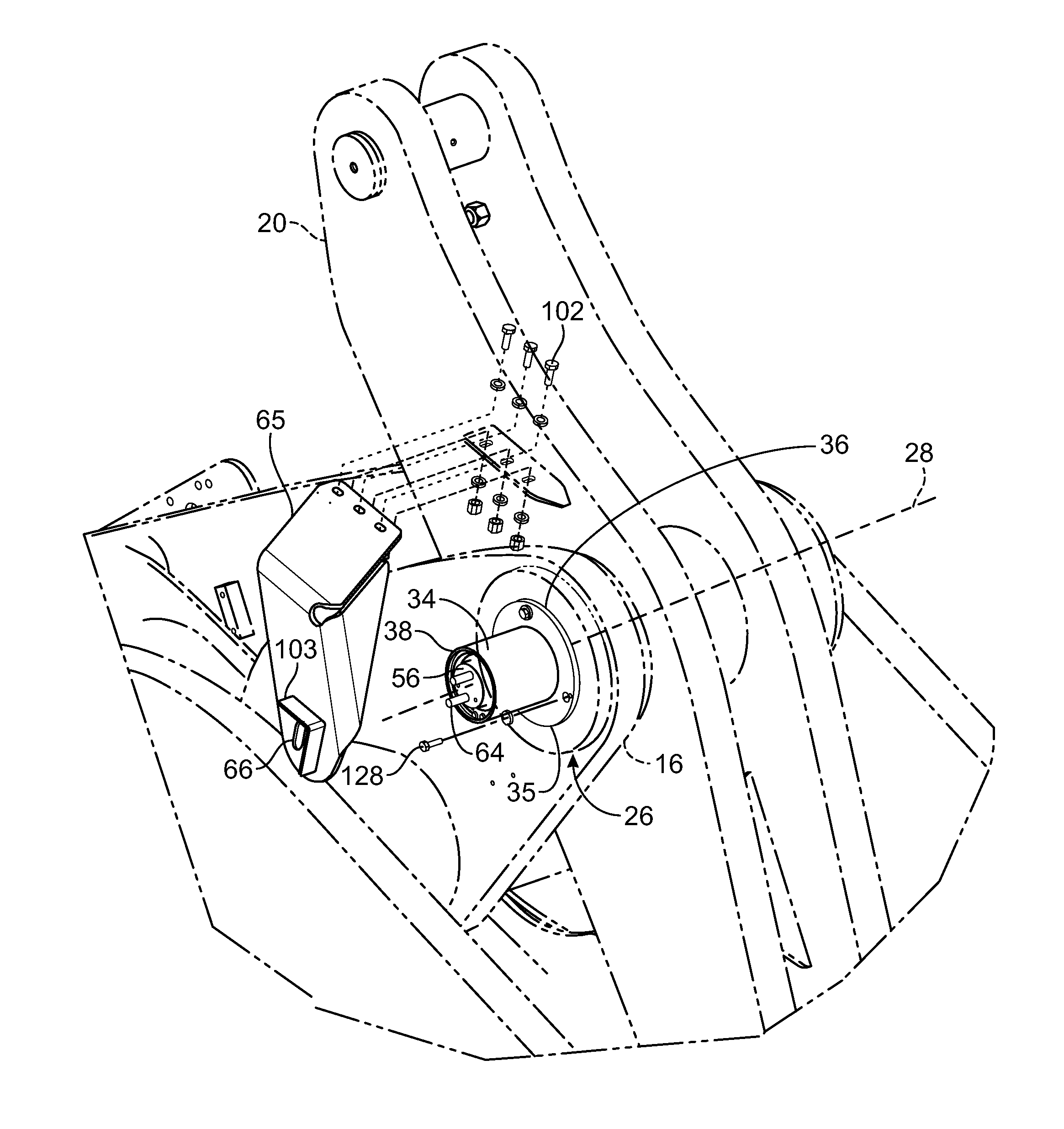
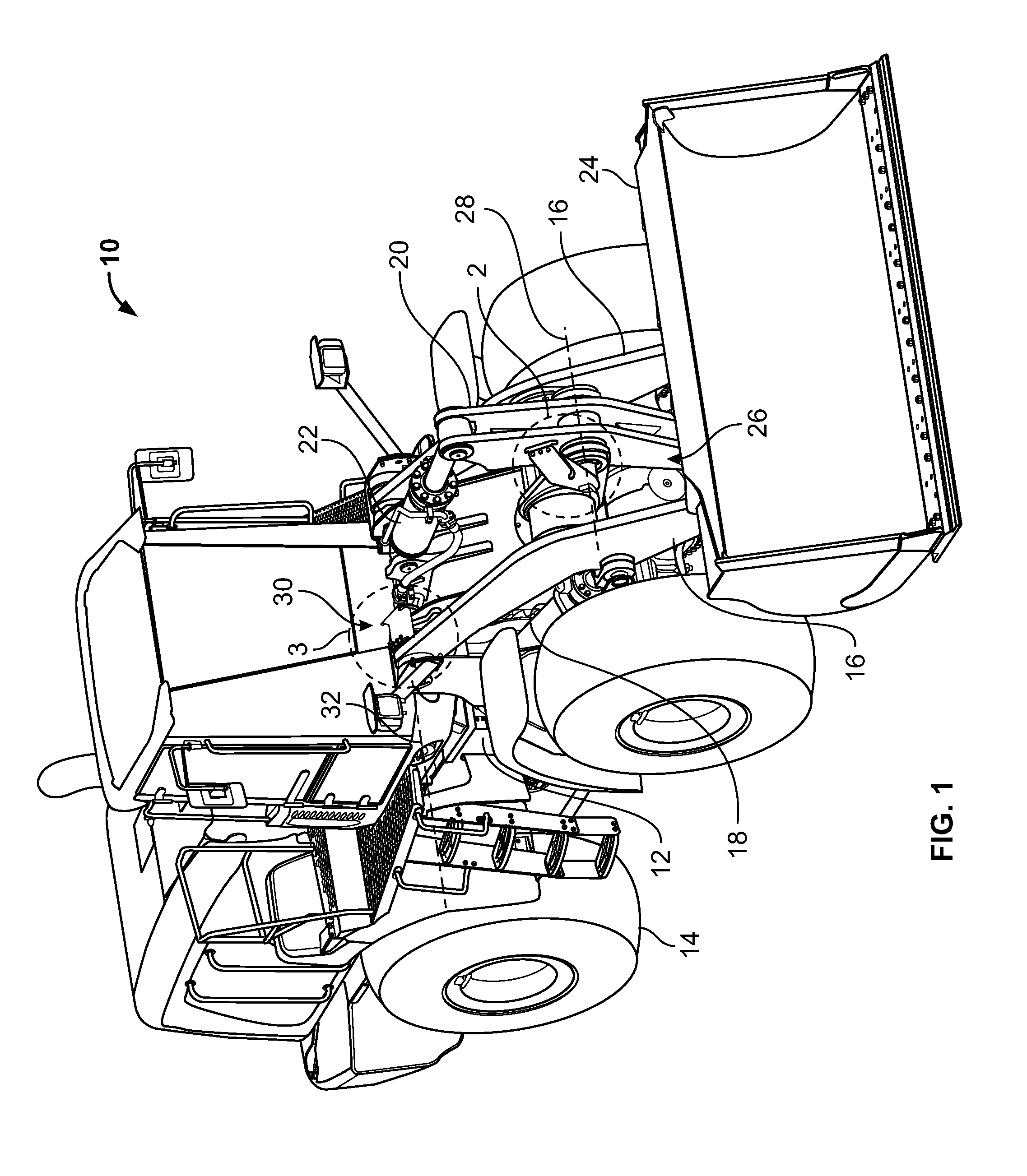
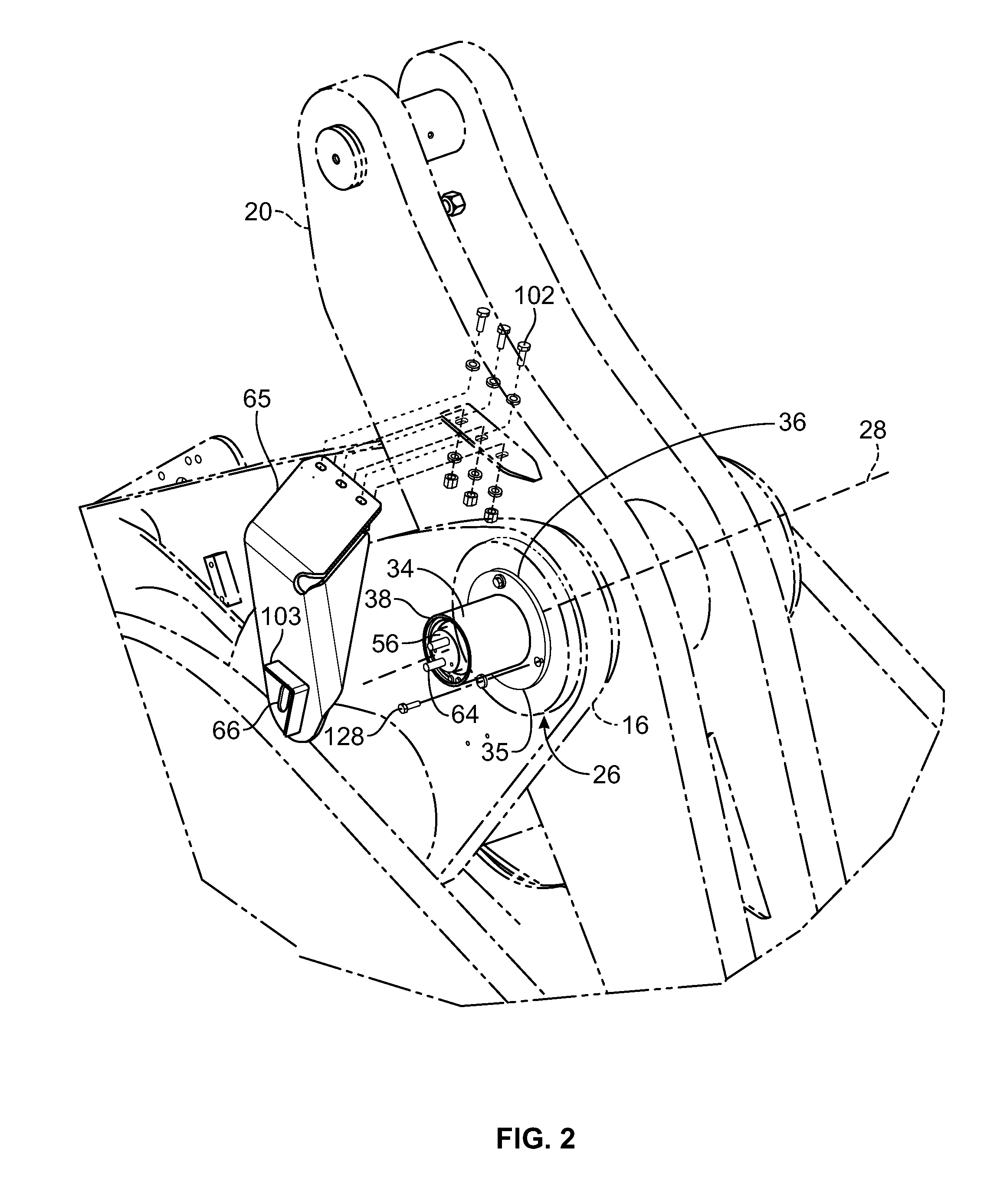
[0018]Referring to the drawings, FIG. 1 shows a machine, such as a work vehicle 10 having a frame 12 that is movably carried by wheels 14. Frame 12 supports articulated linkages, such as a pair of lifting arms 16 that is urged into movement by hydraulic rams 18. Lifting arms 16 pivotably support a bell crank 20 that is urged into movement by hydraulic ram 22. The combination of articulating movement by lifting arms 16 and bell crank 20 control the position and orientation of an implement 24, such as a bucket. A rotary sensor assembly 26 measures angular rotation about an axis 28 between bell crank 20 and lifting arms 16. A rotary sensor assembly 30 measures angular rotation about an axis 32 between frame 12 and lifting arms 16. From this information, the location of lift arms 16, bell crank 20 and the orientation and position of implement 24 can be determined.

[0019]As shown in FIG. 2, which is taken from region 2 of FIG. 1, a rotational axis 28 defines a pivot joint between bell cra...


PUM


Abstract

A sensor assembly for measuring relative rotary movement about a pivot joint having an axis of rotation between a first member and a second member.

Description

FIELD OF THE INVENTION[0001]The present invention relates generally to the field of sensor assemblies. It relates more particularly to rotary sensor assemblies measuring relative angular movement between two members about an axis of rotation.BACKGROUND OF THE INVENTION[0002]Articulated machines having members that rotate with respect to each other are used in many applications. For example, a wheel loader includes lift arms that not only pivot with respect to the wheel loader frame, but also has multiple pivoting connections with an implement, such as a bucket. It is desirable to have sensors that can measure the angular movement of pivot joints from which the position of the members can be determined, including the ability to measure the tilt angle of the bucket. Mechanical components that directly couple two pivoting members to a rotary sensor may be used. However, while rotary sensors used in sensor assemblies may be positioned to measure a relative rotational movement of one mem...

Claims


Application Information

Patent Timeline
IPC IPC(8): G01B5/24
CPCG01D5/34738G01D11/02
Inventor BROSZ, CHRISTOPHER JERELNIEDZIOLKA, OLAFRENARD, MARK ALLANBARES, MICHAEL SYLVESTERJOHNSON, BRADROEHRICH, SHANNON PETER
Owner BLUE LEAF I P
Learn More