Lath Furring Strips

Active Publication Date: 2013-10-03
RUTHERFORD ROBERT B
View PDF17 Cites 16 Cited by
  • Summary
  • Abstract
  • Description
  • Claims
  • Application Information

AI Technical Summary

Benefits of technology

[0030]In another embodiment of a lath furring strip for use with an insulation layer, the lath furring strip is integrated with a weep screed leg. The weep screed has a first weep screed leg extending away from the bottom mounting plate at an obtuse angle. There is provided a second weep screed leg which is contiguous with the first weep screed leg, which extends acutely from the first weep screed leg. The weep screed forms an open triangular-like shape, with the open part facing toward the wall when the furring strip is installed substantially flush against the wall. There may be provided an extension plate extending angularly from the second weep screed leg for placement of the extension plate substantially flush against the wall. This embodiment prevents water from wicking up into the exterior plaster wall, and also allows water that may get into the walls to migrate out, and has the additional features of allowing enough space to place an insulation layer between the lath and the to mounting plate of the furring strip.
[0031]In another embodiment of a lath furring strip for use with an insulation layer, the lath furring strip is integrated with a termination stop. The termination stop has a termination stop leg which extends substantially perpendicular to the bottom mounting plate, and substantially parallel to the mounting leg. The termination stop leg has a greater length than the mounting leg. There may be provided a termination stop leg extension which is substantially perpendicular to the termination stop leg. This provides an effective method of achieving stop points commonly used around windows or doors.
[0032]In another embodiment, the lath furring strip for use with an insulation layer can be designed for use around an outside corner of a wall. There is provided a first mounting plate having an interior side that is substantially planar, for placement substantially flush against the wall and an exterior side for placement of the insulation layer. There is also a second mounting plate having an interior side that is substantially planar, which has an interior side for placement substantially flush against the wall and a second exterior side for placement of the insulation layer. The second mounting plate is substantially perpendicular to the first mounting plate. This lath furring strip also has a

Problems solved by technology

In wall construction, plaster is generally applied to a flexible lath material instead of directly attaching the lath to a rigid structure, such as sheathing, because the current means of attaching a lath directly to a rigid structure can cause cracks.
This penetration creates holes which diminish the waterproofing features of the moisture barrier.
Since plaster is water absorbent, it can transmit water to more expensive and structurally important components of the building, such as the sheathing or the framing.
However, there are still problems with current lath furring strips.
A problem with adding additional waterproofing layers to the furring strip is that any additional waterproofing on the furring strip would increase the profile height of the lath furring strip.
However, one drawback of using a lath furring strip with a profile of less than ⅜ of an inch is that it may reduce the attachment strength on the furring strip where the lath is secured.
Although one might consider reducing the side of the attachment hole on the mounting leg, it takes skill insert wire ties th

Method used


Image

  • Lath Furring Strips
  • Lath Furring Strips
  • Lath Furring Strips

Examples


Embodiment Construction

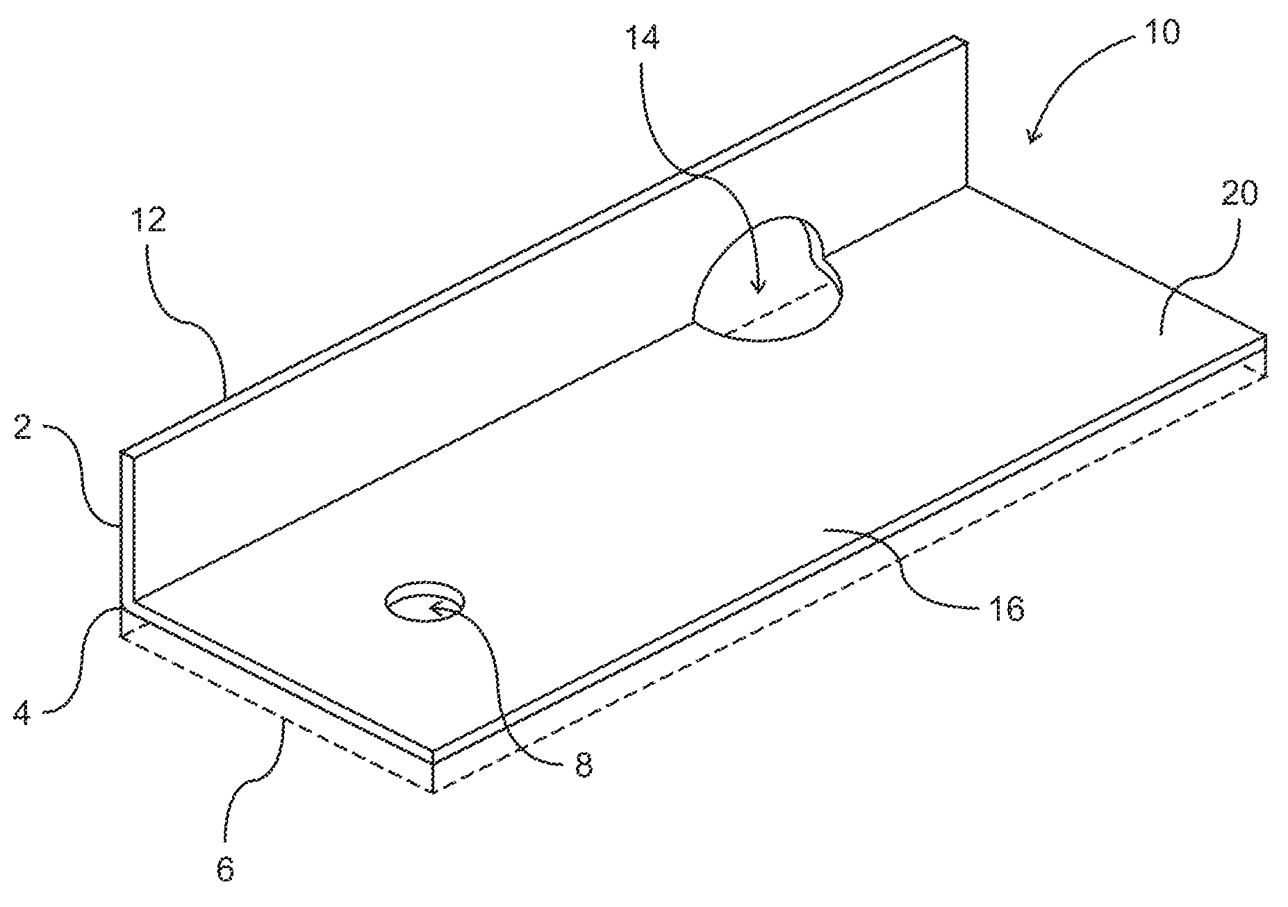
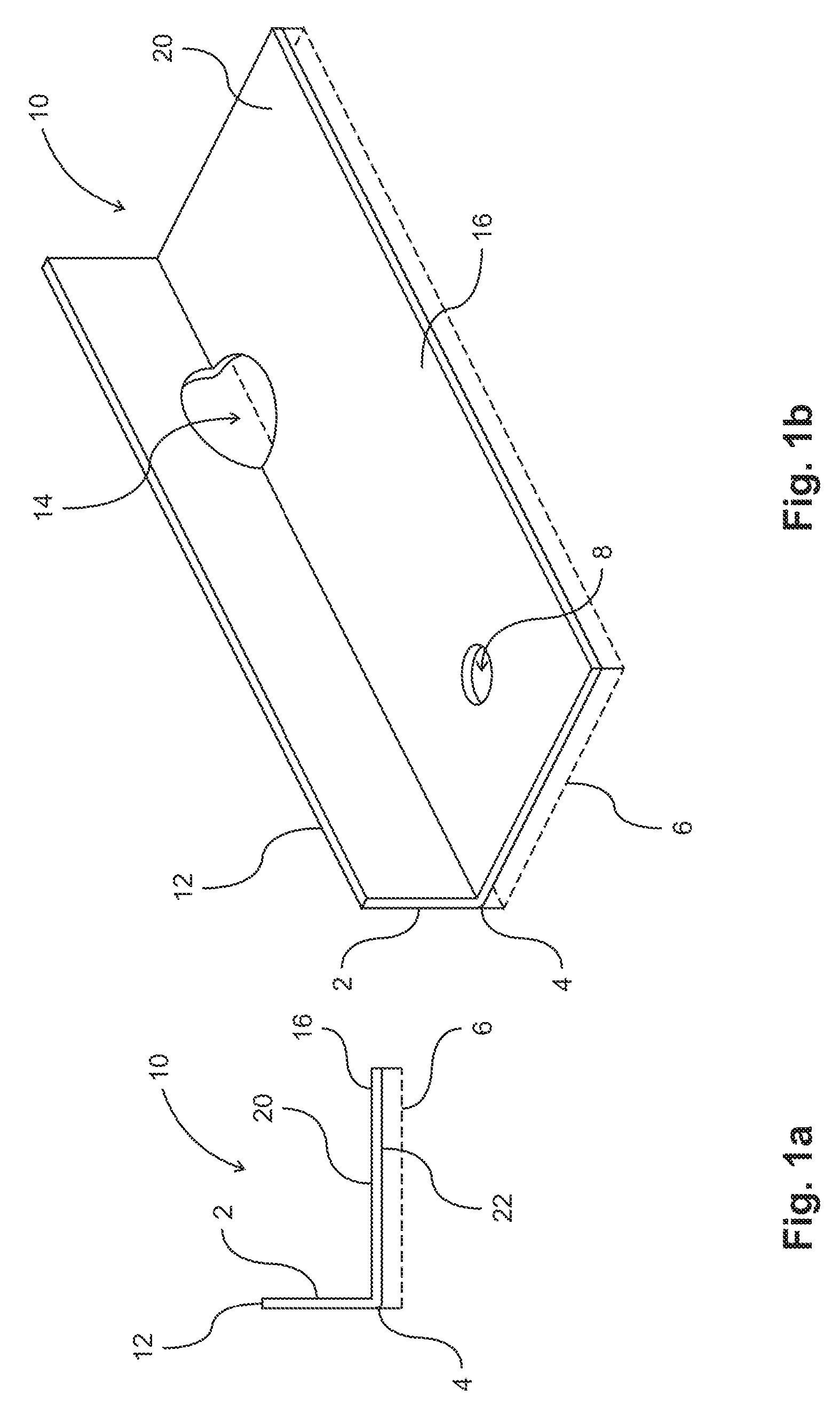
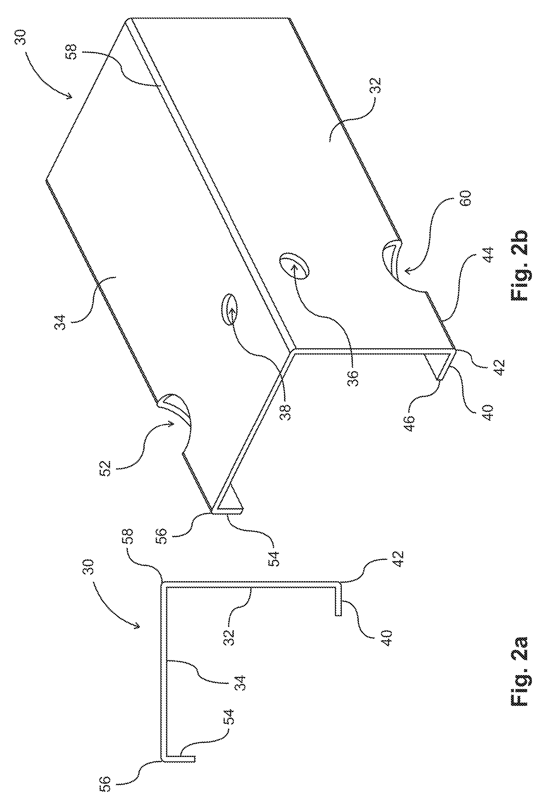
[0077]The following description is of the best-contemplated mode of carrying out the invention. This description is made for the purpose of illustrating the general principles of the invention and should not be taken in a limiting sense. The scope of the invention is best determined by reference to the appended claims. Preferable embodiments of the present invention are described with reference to the FIGS. 1-20. FIG. 1, FIG. 5, and FIG. 6 show various embodiments of increasing the waterproofing characteristics of the lath furring strip. FIG. 2, FIG. 3, and FIG. 4 show various embodiments of the shape of the lath furring strip without any waterproofing elements, but can incorporate the waterproofing elements of the embodiments in any other figure. FIG. 7 and FIG. 8 show various embodiments of how the lath furring strip and lath are assembled, and may incorporate any of the waterproofing or lath shapes in any of other figures. FIG. 9, FIG. 10, FIG. 11, FIG. 12, FIG. 13, and FIG. 14 s...


PUM


Abstract

The present invention provides a lath furring strip having improved water-resistant and insulation features. The lath furring strip has portions of the mounting leg height not exceeding 0.365 inches for proper plastering of a wall. The lath furring strip is integrated into other architectural structures such as reveals, expansion joints and window flange coverings. By integrating these structures with a lath furring strip having water proofing features, there is increased water proofing of the entire architectural structure. One or more moisture barriers can easily be applied to the wall or furring strips that prevents seepage of moisture from the stucco on the lath to a wall or framing. By using an improved lath furring strip, fewer penetrations are needed to secure the furring strip to a wall compared to securing a lath directly to a wall.

Description

CROSS-REFERENCE TO RELATED APPLICATIONS[0001]This continuation in part application claims the benefit of continuation in part patent application Ser. No. 13 / 455,046 filed on Apr. 24, 2012, which claims benefit of patent application Ser. No. 13 / 433,247 filed on Mar. 28, 2012, all of which are herein incorporated by reference.FIELD OF THE INVENTION[0002]This invention relates to lath furring strips. In particular, this invention relates to lath furring strips with improved water resistance and for accommodating insulation layers.BACKGROUND OF THE INVENTION[0003]The present invention is directed to overcoming problems associated with securing a lath to a sheathing (or a wall structure). In wall construction, plaster is generally applied to a flexible lath material instead of directly attaching the lath to a rigid structure, such as sheathing, because the current means of attaching a lath directly to a rigid structure can cause cracks. By applying plaster to a metal lath (which include ...

Claims


Application Information

Patent Timeline
IPC IPC(8): E04F13/073E04B1/38E04F13/04
CPCE04F13/06E04F13/068
Inventor RUTHERFORD, ROBERT B.
Owner RUTHERFORD ROBERT B
Why Eureka
Try Eureka