Power tool

a technology of power tools and power cases, applied in the field of power tools, can solve problems such as degradation of the durability of the power tools, and achieve the effects of reducing the strength of the hammer case, reducing the durability of the power tools, and high flow resistan

Inactive Publication Date: 2013-10-03
HITACHI KOKI CO LTD
View PDF3 Cites 12 Cited by
  • Summary
  • Abstract
  • Description
  • Claims
  • Application Information

AI Technical Summary

Benefits of technology

[0009]Since the air release passage described in Patent Document 1 has the labyrinth shape, its flow resistance is high. The pressure adjusting mechanism described in Patent Document 2 largely jetties toward the inside of a gear housing. Therefore, when this pressure adjusting mechanism is adopted in a power tool provided with a planetary gear mechanism, the overall length of the power tool is required to be made longer so as to avoid interference between the planetary gear and

Problems solved by technology

As described in Patent Document 3, when a through hole is formed in a hammer case, the strengt

Method used


Image

  • Power tool
  • Power tool
  • Power tool

Examples


Embodiment Construction

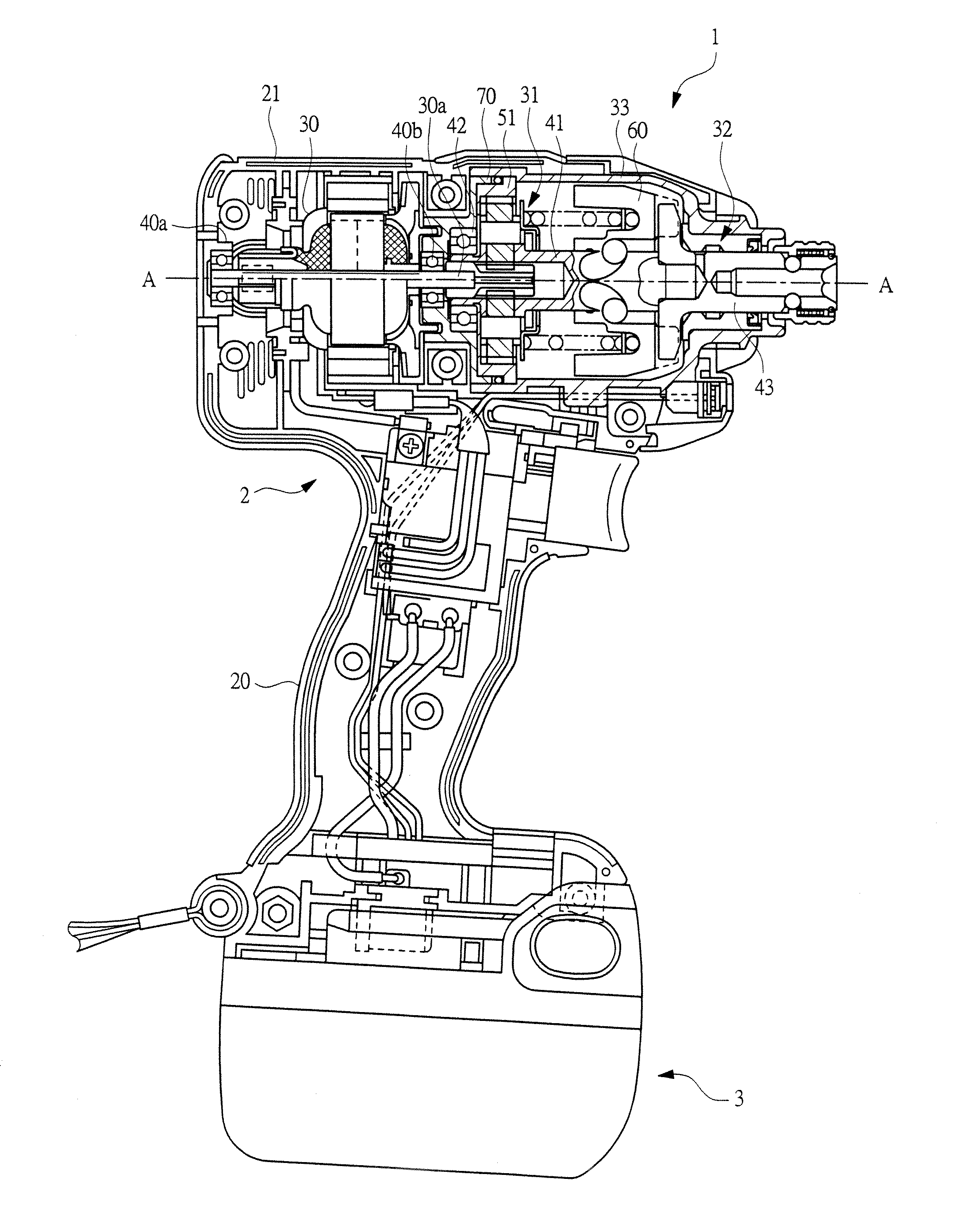
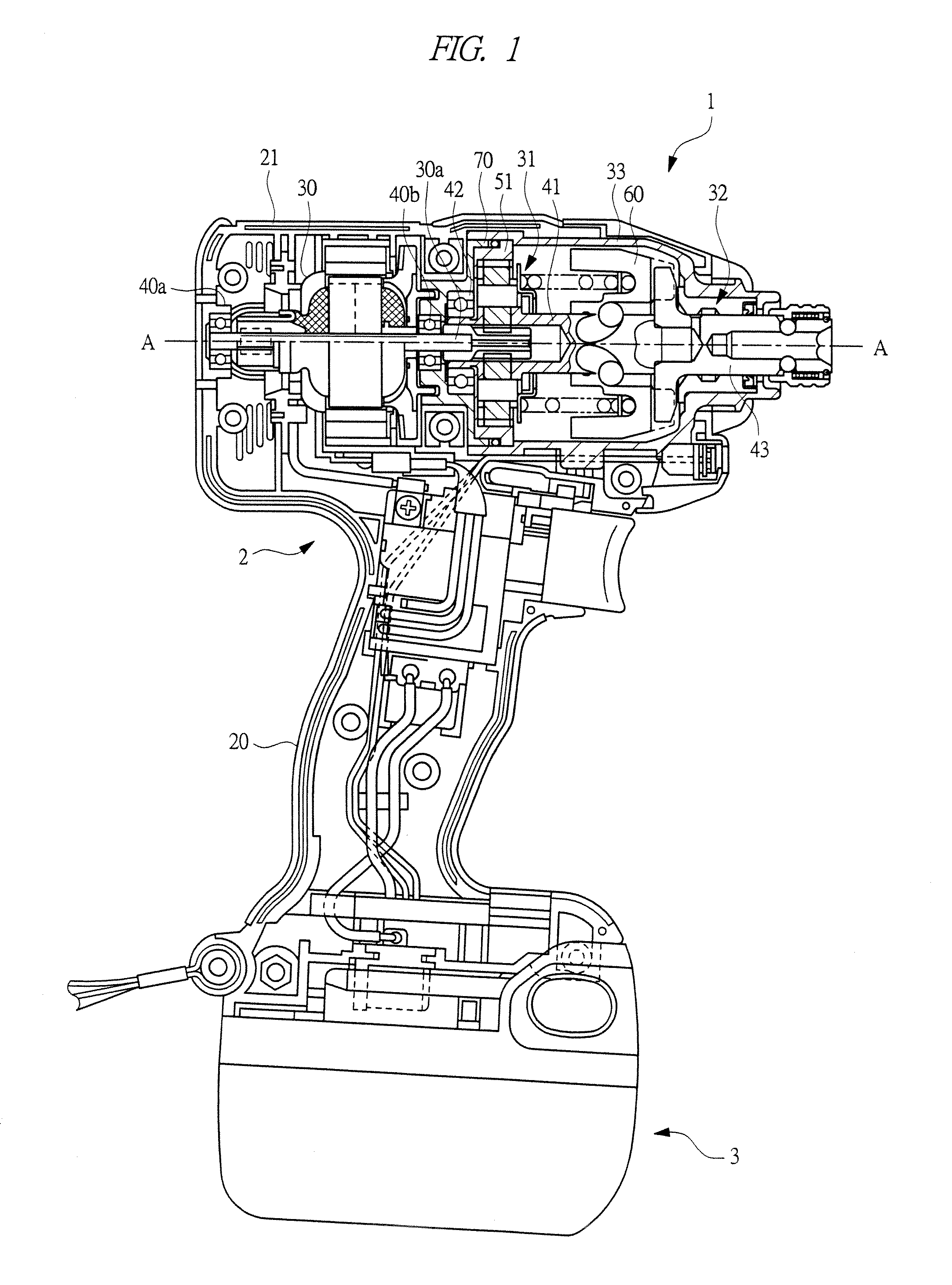
[0016]The following description will explain one example of an embodiment of the present invention in detail. FIG. 1 is a longitudinal cross-sectional view illustrating an impact driver 1 in which the present invention is adopted. To the impact driver 1, a driver bit (not illustrated) serving as a tip tool is attached. Moreover, the impact driver 1 is provided with a transmission mechanism that transmits power to the driver bit attached to the impact driver 1. At the time of use of the impact driver 1, a rotary impact force is applied to a screw member that is a subject to be fastened by the driver bit.

[0017]As illustrated in FIG. 1, the impact driver 1 includes a housing 2 and a battery case 3 that is detachably attached to the housing 2. Therefore, this impact driver 1 is a cordless device or a portable device.

[0018]The housing 2 has a handle unit 20 to be grabbed by a worker, that is, an operator, and a body unit 21 having a cylindrical shape that is integrally molded with one en...


PUM


Abstract

A power tool, in which a case that is connected to a housing and the case houses a reducer mechanism that decelerates an output of an electric motor and an impact mechanism that transmits an output of the reducer mechanism to a tip tool, is provided. The power tool further includes an inner cover that covers an opening of the case, a ring gear included in the reducer mechanism, a spindle that is rotatably supported by a bearing, and a space portion that is placed between the inner cover and the ring gear and in a periphery of the bearing, and capable of stocking grease. A through hole, which communicates with the inside and outside of the case through the space portion, is formed in the inner cover.

Description

CROSS-REFERENCE TO RELATED APPLICATION[0001]The present application claims priority from Japanese Patent Application No. 2012-070602 filed on Mar. 27, 2012, the content of which is hereby incorporated by reference into this application.TECHNICAL FIELD OF THE INVENTION[0002]The present invention relates to a power tool in which a tip tool is driven by a driving source, such as an electric motor, a pneumatic pressure motor, or the like.BACKGROUND OF THE INVENTION[0003]As one example of the power tool in which a tip tool is driven by a driving source, such as an electric motor, a pneumatic pressure motor, or the like, an impact driver, an impact wrench or the like has been known. A driver bit and a socket serving as tip tools are attached to the impact driver and the impact wrench. The tip tool to be attached to the impact driver and the impact wrench is driven to rotate and an impact force (impact) is applied thereto.[0004]The above-mentioned power tool is provided with a driving sour...

Claims


Application Information

Patent Timeline
IPC IPC(8): B25F5/00
CPCB25F5/001B25B21/02
Inventor TAKAHASHI, SHIGERUOOMORI, KATSUHIRONISHIKAWA, TOMOMASA
Owner HITACHI KOKI CO LTD
Why Eureka
Try Eureka