System and method for determining attachment and polarity of a welding electrode

a technology of attachment and polarity, which is applied in the field of welding systems, can solve the problems of poor quality welds and reduce and achieve the effect of reducing the efficiency and operability of the welding system

Active Publication Date: 2013-10-03
ILLINOIS TOOL WORKS INC
View PDF16 Cites 62 Cited by
  • Summary
  • Abstract
  • Description
  • Claims
  • Application Information

AI Technical Summary

Benefits of technology

[0004]Proper operation of the welding systems may rely on the knowledge of an operator to make appropriate electrode connections within the welding system. Unfortunat

Problems solved by technology

Unfortunately, an improper electrode connection may result in a poor quality weld with a

Method used


Image

  • System and method for determining attachment and polarity of a welding electrode
  • System and method for determining attachment and polarity of a welding electrode
  • System and method for determining attachment and polarity of a welding electrode

Examples


Embodiment Construction

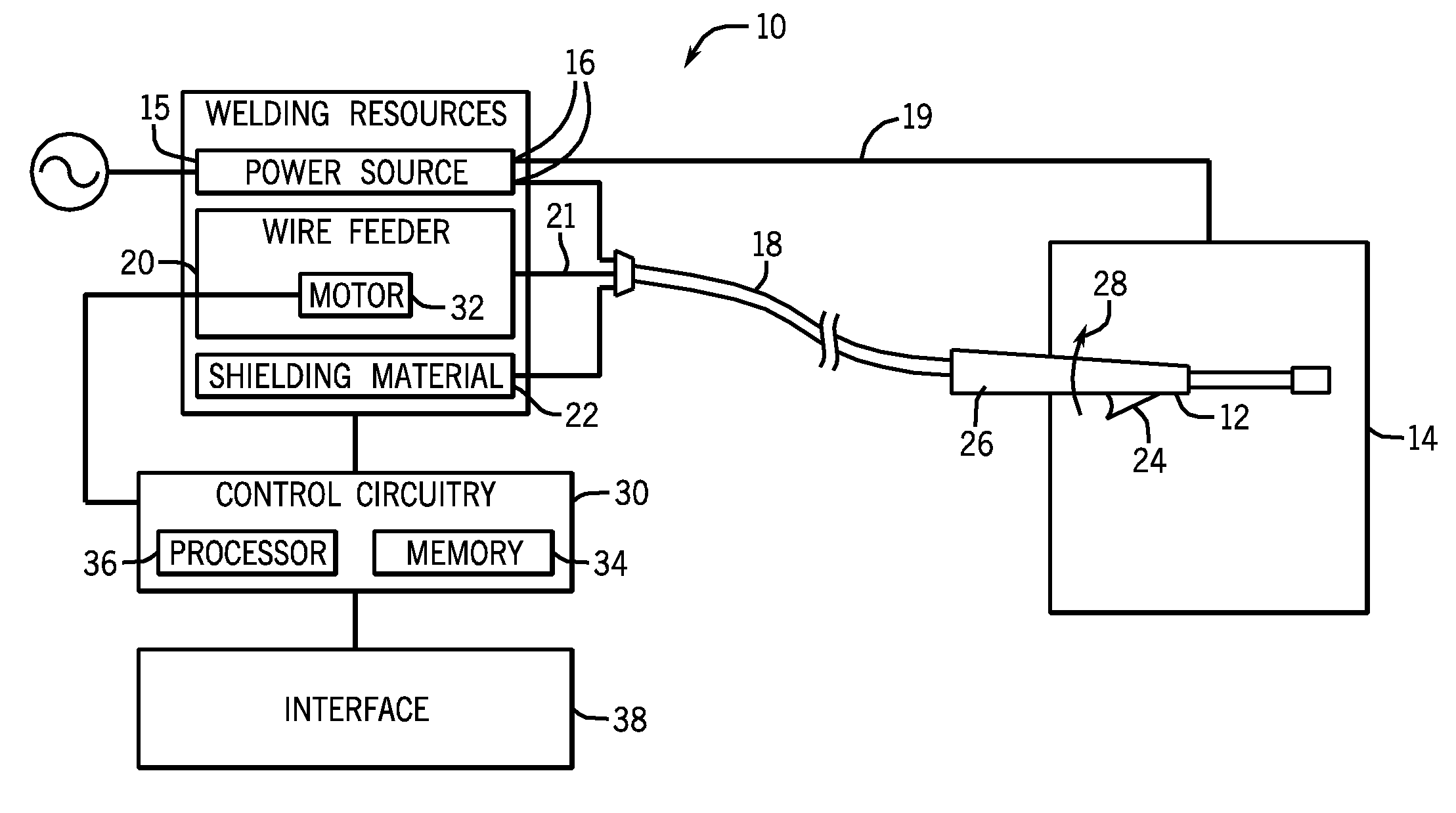
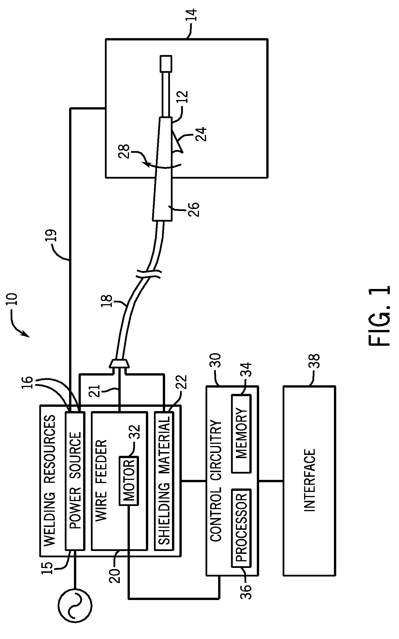
[0014]The present disclosure is directed towards systems and methods for determining the attachment and polarity of welding electrodes. In general, the efficiency of a welding operation may be affected by the attachment of welding electrodes to a power supply. If the welding electrodes are improperly connected (e.g., if one of the welding electrodes is not connected, or if the polarity of the welding electrodes is reversed), the welding operation may be adversely affected. Accordingly, an operator interface may alert an operator of the improper connection, and the operator may take corrective action (e.g., by connecting the unconnected welding electrode, or by correcting the polarity of the welding electrodes) to improve the efficiency of the welding operation.

[0015]Turning now to the figures, FIG. 1 illustrates an exemplary welding system 10 that includes a welding torch 12 and a work piece 14. A power source 15 includes multiple studs 16 that may accommodate one or more welding el...


PUM

PropertyMeasurementUnit
Poweraaaaaaaaaa
Polarityaaaaaaaaaa
Electric potential / voltageaaaaaaaaaa

Abstract

A welding system includes a power source configured to generate power and deliver the power to a welding electrode. The power source comprises a positive stud and a negative stud. The welding system also includes control circuitry configured to determine whether the welding electrode is properly connected to the positive and negative studs of the power source.

Description

CROSS-REFERENCE TO RELATED APPLICATIONS[0001]This application is a Non-Provisional Patent Application of U.S. Provisional Patent Application No. 61 / 616,303, entitled “System and Method for Determining Attachment and Polarity of a Welding Electrode”, filed on Mar. 27, 2012, which is herein incorporated by reference.BACKGROUND[0002]The present disclosure generally relates to welding systems, and more specifically, to systems and methods to improve the operability of welding systems.[0003]A wide range of welding systems and welding control regimes have been implemented for various purposes. For example, metal inert gas (MIG) techniques allow for formation of a continuing weld bead by feeding welding wire shielded by inert gas from a welding torch. Electrical power is applied to the welding wire and a circuit is completed through the workpiece to sustain an arc that melts the wire and the workpiece to form the desired weld.[0004]Proper operation of the welding systems may rely on the kn...

Claims


Application Information

Patent Timeline
IPC IPC(8): B23K9/095G01R31/50
CPCG01R31/02H02H11/00B23K9/10B23K9/32B23K9/0956G01R31/041B23K9/1006B23K37/006G01R31/67G01R31/50
Inventor KNOENER, CRAIG STEVENWOODWARD, RONALD DEWAYNE
Owner ILLINOIS TOOL WORKS INC
Why Eureka
Try Eureka