
Systems and Methods for Balancing UPS Source Currents During Unbalanced Load Transient Conditions

a source current and load technology, applied in power conversion systems, ac-ac conversion, circuit arrangements, etc., can solve problems such as inability to provide uninterrupted power to load devices, power drawn from dc bus voltage fluctuation, and input ac source current may no longer be constan

Inactive Publication Date: 2013-10-03
GENERAL ELECTRIC CO
View PDF0 Cites 30 Cited by
  • Summary
  • Abstract
  • Description
  • Claims
  • Application Information

AI Technical Summary

Benefits of technology

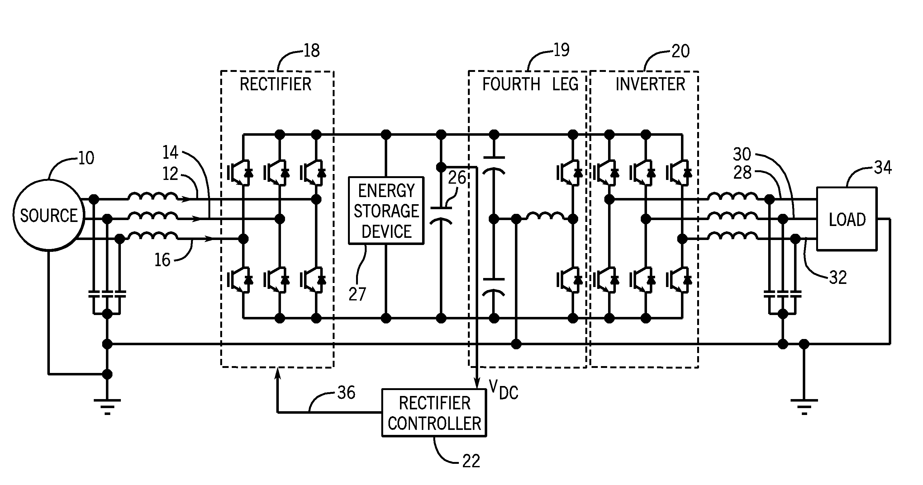
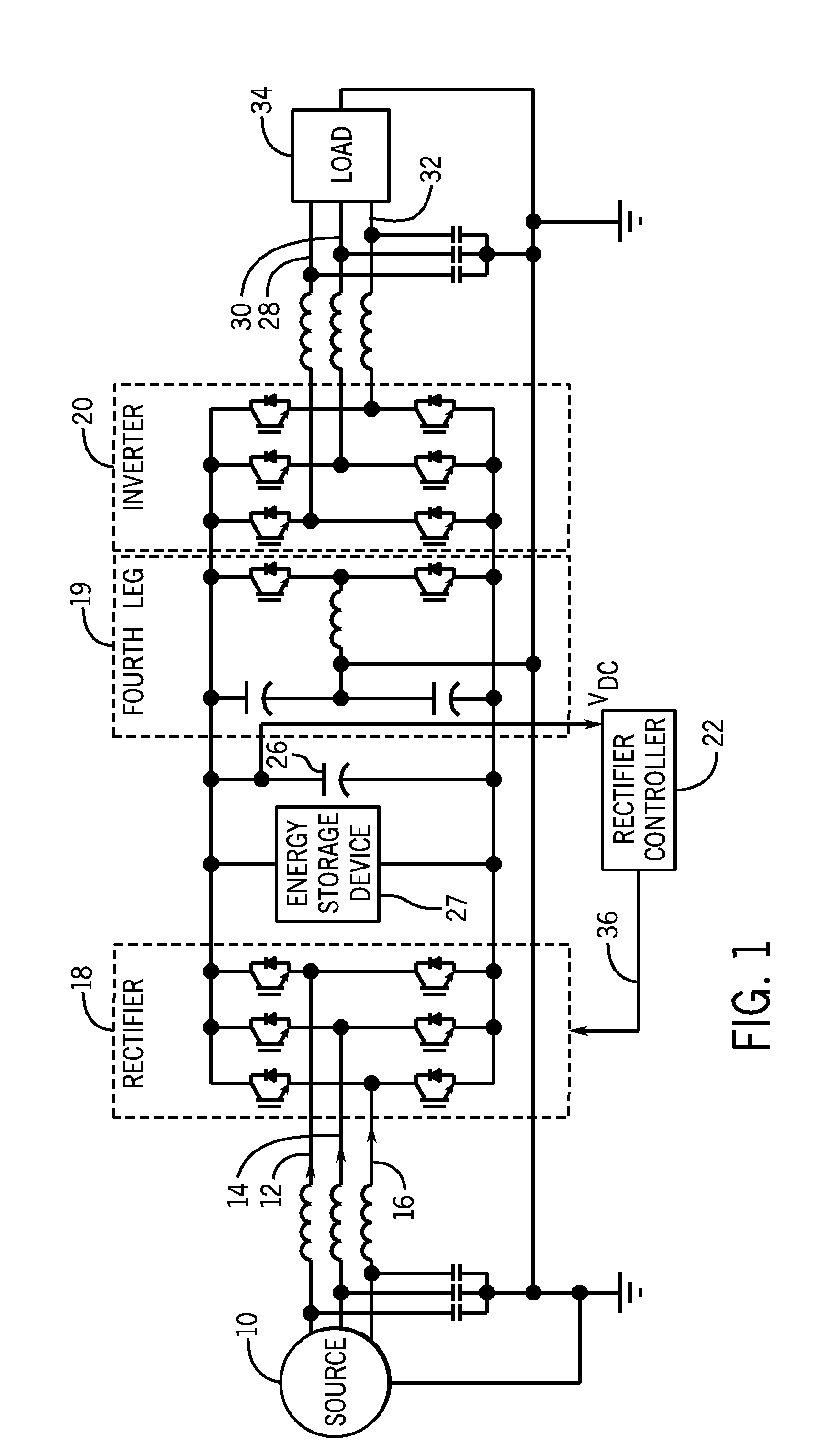
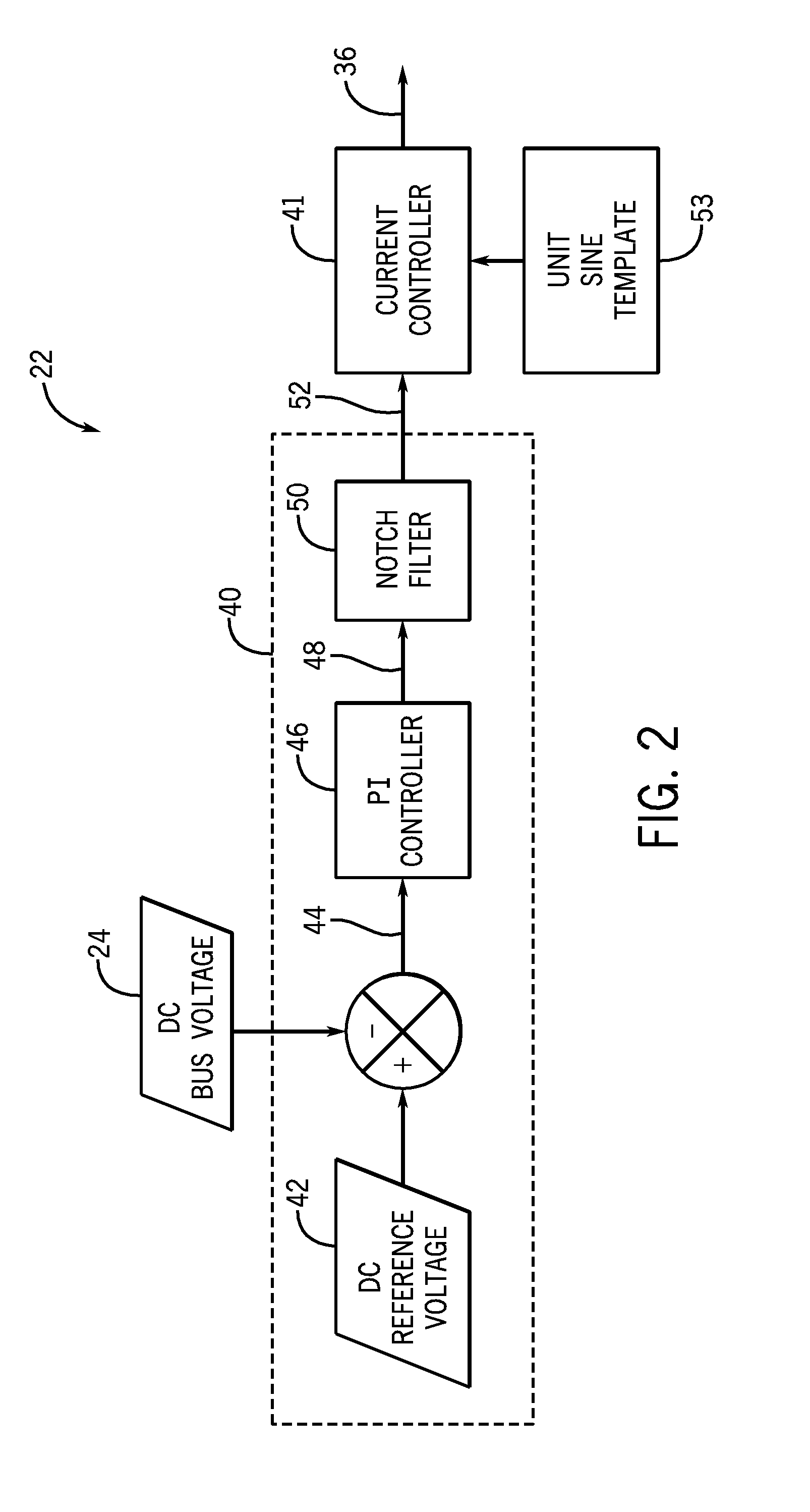
The invention is a system and method for balancing current from an AC source using a UPS and a rectifier with switching components. The system includes a rectifier that converts the first AC voltage into a DC voltage, an inverter that converts the DC voltage into a second AC voltage, and a rectifier controller that determines the difference between the DC voltage and a reference voltage, filters a second order harmonic from the difference, and generates a filtered error. The filtered error is then used to determine one or more switching signals for the switching components in the rectifier. The technical effect of the invention is to improve the stability and efficiency of the power conversion process.

Problems solved by technology

In this manner, the UPS may provide uninterrupted power to load devices when its input AC power source becomes unavailable.
However, once the inverter load of the UPS becomes unbalanced, the power drawn from the DC bus voltage may fluctuate and the input AC source currents may no longer be constant.
On the front-end rectifier side, the fluctuating DC bus voltage (i.e., ripple corrupted DC voltage) is input to the rectifier controller, which subsequently generates irregular firing signals for the front-end rectifier that results in unbalanced source currents and high total harmonic distortion (THD) in the source currents.
Unfortunately, the high THD in the source current may have detrimental effects on the input AC source and the UPS.

Method used


Image

  • Systems and Methods for Balancing UPS Source Currents During Unbalanced Load Transient Conditions
  • Systems and Methods for Balancing UPS Source Currents During Unbalanced Load Transient Conditions
  • Systems and Methods for Balancing UPS Source Currents During Unbalanced Load Transient Conditions

Examples


Embodiment Construction

[0015]This written description uses examples to disclose the invention, including the best mode, and also to enable any person skilled in the art to practice the invention, including making and using any devices or systems and performing any incorporated methods. The patentable scope of the invention is defined by the claims, and may include other examples that occur to those skilled in the art. Such other examples are intended to be within the scope of the claims if they have structural elements that do not differ from the literal language of the claims, or if they include equivalent structural elements with insubstantial differences from the literal languages of the claims.

[0016]When introducing elements of various embodiments of the present invention, the articles “a,”“an,”“the,” and “said” are intended to mean that there are one or more of the elements. The terms “comprising,”“including,” and “having” are intended to be inclusive and mean that there may be additional elements ot...


PUM


Abstract

Systems and methods for balancing current from an AC source. The method includes determining a difference between a DC voltage output by a rectifier in an uninterruptible power supply (UPS) to a DC reference voltage. The method also includes determining an error between the DC voltage and the DC reference voltage based at least in part on the difference. After determining the error, the method includes filtering a second order harmonic from the error thereby generating a filtered error. The method may then include determining one or more switching signals for one or more switching components in the rectifier based at least in part on the filtered error and sending the switching signals to the rectifier.

Description

BACKGROUND OF THE INVENTION[0001]The subject matter disclosed herein relates to an uninterruptible power supply (UPS), and more particularly, to improving the total harmonic distortion (THD) of source currents for a UPS during unbalanced load conditions.[0002]A UPS system, such as a 3-phase stiff double conversion UPS system, may include a front-end rectifier, a direct current (DC) link with a capacitor and an energy storage device, and an inverter. The UPS system may use the front-end rectifier to convert source alternating current (AC) power into DC power that may be supplied to the DC link. The DC link may then provide the DC power to the capacitor, the energy storage device, and the inverter. The inverter may convert the DC power back to AC power, which may then be used to power a load device. If the AC power input into the front-end rectifier becomes unavailable, the energy storage device may act as a DC battery for the inverter, and the inverter may continue to provide AC powe...

Claims


Application Information

Patent Timeline
IPC IPC(8): H02M1/12H02M5/458
CPCH02J3/26H02M7/219Y02E40/50H02M1/12H02J9/062
Inventor COLOMBI, SILVIOKOLHATKAR, YASHOMANI Y.PIEMONTESI, MARCOPRASAD, MALAVALLI NANJUNDASWAMY LAKSHMISTROZZI, LAURO
Owner GENERAL ELECTRIC CO
Features
  • Generate Ideas
  • Intellectual Property
  • Life Sciences
  • Materials
  • Tech Scout
  • Unparalleled Data Quality
  • Higher Quality Content
  • 60% Fewer Hallucinations
Learn More