Transonic Blade

a technology of transonic blades and blades, applied in the direction of supersonic fluid pumps, machines/engines, liquid fuel engines, etc., can solve the problems of restricting and achieve the effect of increasing the stall margin and reducing the loss

Active Publication Date: 2013-10-03
MITSUBISHI POWER LTD
View PDF4 Cites 32 Cited by
  • Summary
  • Abstract
  • Description
  • Claims
  • Application Information

AI Technical Summary

Benefits of technology

[0013]The present invention can provide the transonic blade that can increase a stall margin with...

Problems solved by technology

Therefore, an effect of increasing th...

Method used


Image

  • Transonic Blade
  • Transonic Blade
  • Transonic Blade

Examples


embodiment 1

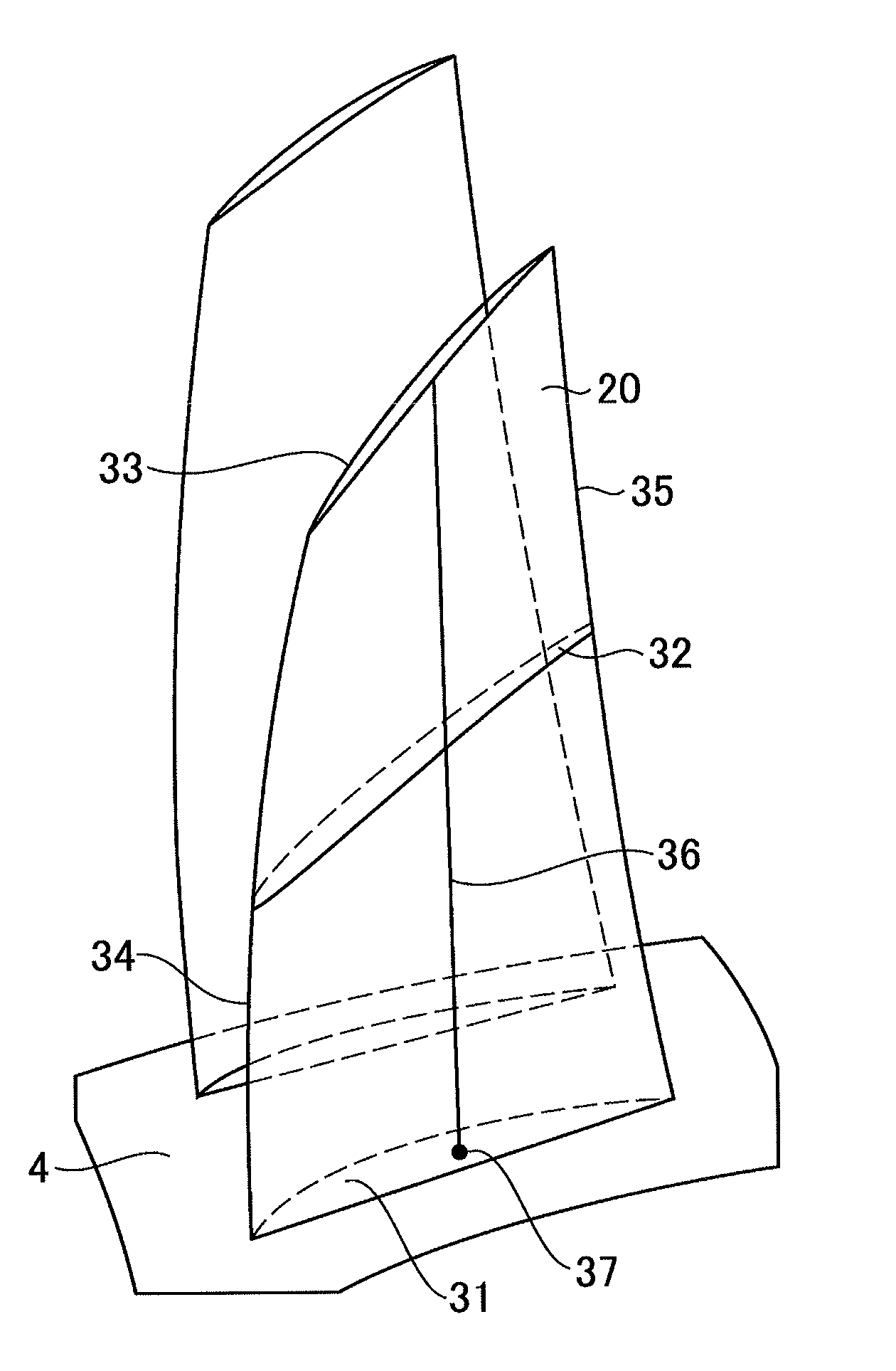
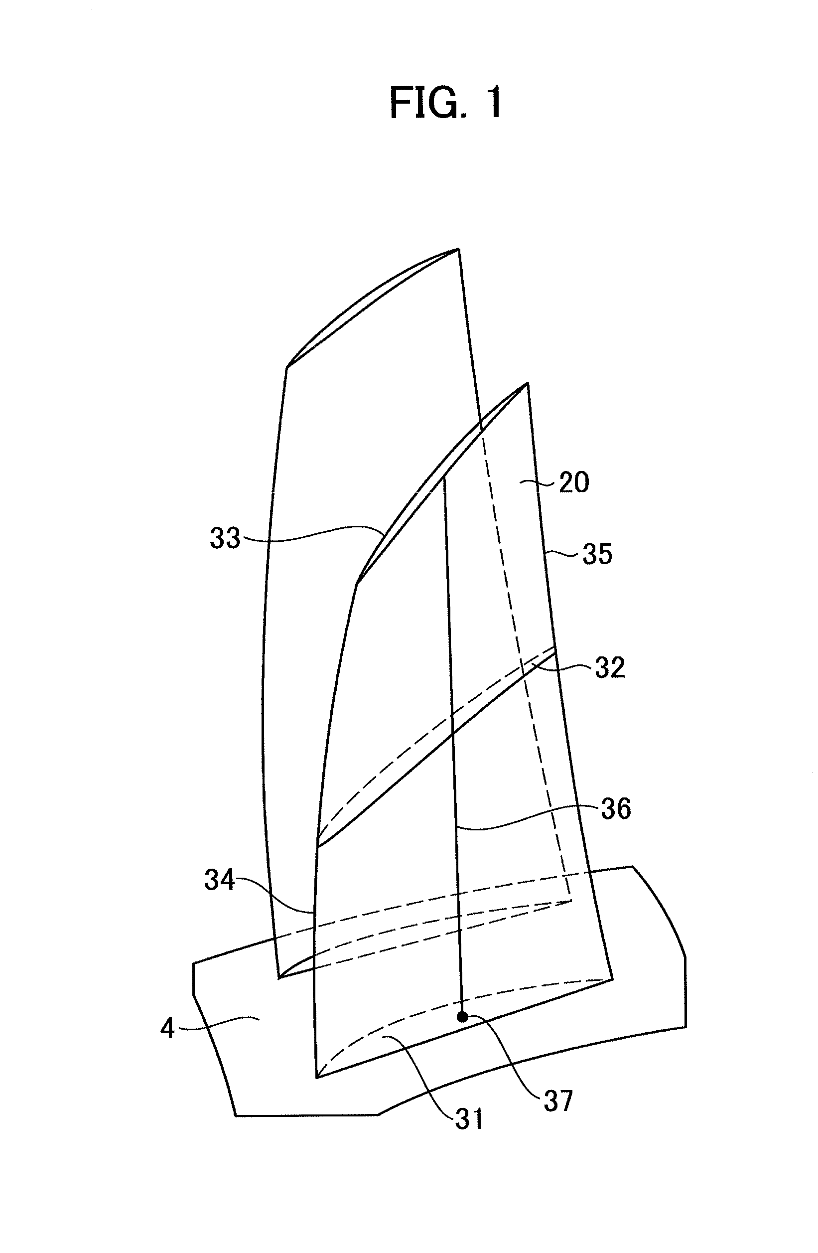
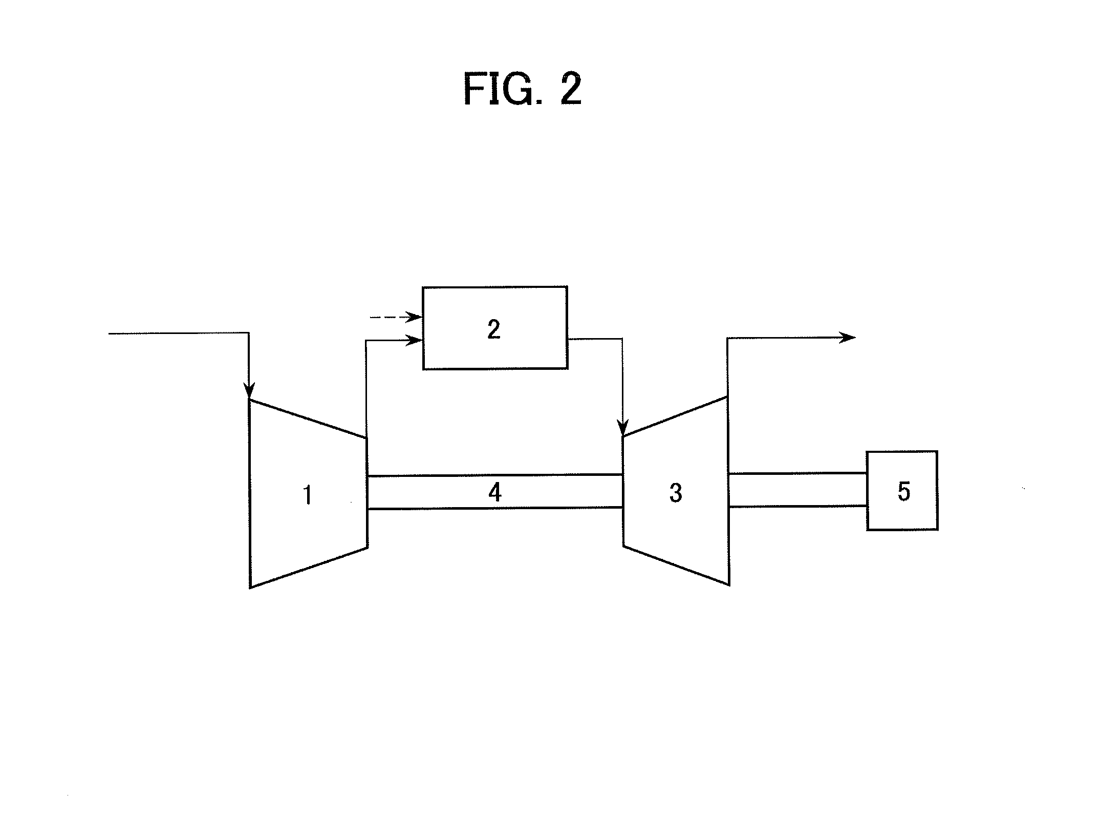
[0035]FIG. 1 is a perspective view of transonic blades according to a first embodiment. FIG. 2 is a cycle configuration diagram of an axial-flow rotating machine into which the transonic blades are built. Incidentally, a gas turbine compressor is here assumed as the axial-flow rotating machine.

[0036]An outline of a cycle is first described with reference to FIG. 2. Working fluid first flows into an axial-flow compressor 1 and compressed therein. The working fluid thus compressed flows into a combustor 2, into which fuel is injected to produce high-temperature combustion gas. The high temperature and pressure combustion gas flows into a turbine 3 to rotate a rotor 4, thereby driving a generator 5 for electrical generation.

[0037]FIG. 3 is a cross-sectional view of the axial-flow compressor 1 taken along a meridional plane. Referring to FIG. 3, the compressor 1 includes a rotor 4 or a rotating shaft; an outer circumferential side casing 12a; an inlet inner circumferential side casing 1...

embodiment 2

[0048]A comparison of the stacking line of a transonic blade according to a second embodiment is shown in FIG. 12. The second embodiment is different from the first embodiment in that the axial position of the stacking line is constant on the hub cross-sectional surface 31 side of a certain spanwise position lying between the hub cross-sectional surface 31 and the mean cross-sectional surface 32 and is monotonously reduced on the tip cross-sectional surface 33 side of such a certain spanwise position. The airfoil of the second embodiment is the same as that of the first embodiment. Incidentally, devices overlapping with those in FIG. 6 are denoted by like reference numerals and their detailed explanations are omitted.

[0049]The transonic blade 20 of the present embodiment has the axial position of the stacking line that does not vary up to a certain spanwise position. Therefore, the axial position in a range from the mean cross-sectional surface 32 to the tip cross-sectional surface ...


PUM


Abstract

The present invention provides a transonic blade that concurrently achieves reduction in shock loss at a design point and improvement in stall margin in blades operating in a flow field of transonic speed or higher in an axial-flow rotating machine. A cross-sectional surface at each of spanwise positions of the blade is shifted parallel to a stagger line connecting a leading edge with a trailing edge of the blade. A stacking line is shifted toward an upstream side of working fluid. The stacking line connects together respective gravity center positions of blade cross-sectional surfaces at spanwise positions in a range from a hub cross-sectional surface joined to a rotating shaft or an outer circumferential side casing of a rotating machine to a tip cross-sectional surface lying at a position most remote from the hub cross-sectional surface in a spanwise direction.

Description

TECHNICAL FIELD[0001]The present invention relates to a transonic blade used in a flow field through which an overall or partial flow passes at a transonic speed or higher and to an axial-flow rotating machine using the transonic blade.[0002]BACKGROUND ART[0003]In the context of the recent increase in fuel cost, the importance of improved efficiency in axial-flow rotating machines has grown, such as industrial gas turbines and jet engines. One of means of improving efficiency in the axial-flow rotating machine is to reduce a blade loss. The blade loss is roughly classified into a profile loss occurring at a radial cross-sectional surface (airfoil) of a blade and the other losses. Examples of the other losses include a shock loss and a secondary loss. The recent axial-flow rotating machines subjected to a large load per one stage have an increased Mach number of working fluid flowing into a blade. Therefore, the shock loss tends to increase. In other words, a reduction in shock loss ...

Claims


Application Information

Patent Timeline
IPC IPC(8): F01D5/14
CPCF01D5/141F04D21/00F01D5/147F05D2210/30Y02T50/673F04D29/324Y02T50/60F04D29/384F05D2240/301F05D2240/302
Inventor MYOREN, CHIHIROTAKAHASHI, YASUOMARUSHIMA, SHINYA
Owner MITSUBISHI POWER LTD
Why Eureka
Try Eureka