Ultrasonic probe, electronic instrument, and ultrasonic diagnostic device
- Summary
- Abstract
- Description
- Claims
- Application Information
AI Technical Summary
Benefits of technology
Problems solved by technology
Method used
Image
Examples
second embodiment
(4) Annular Body Unit
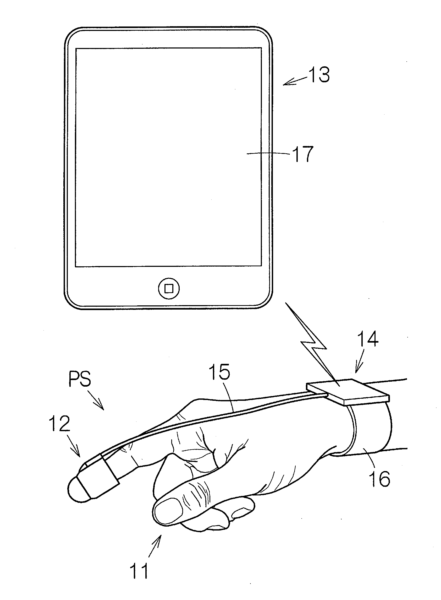
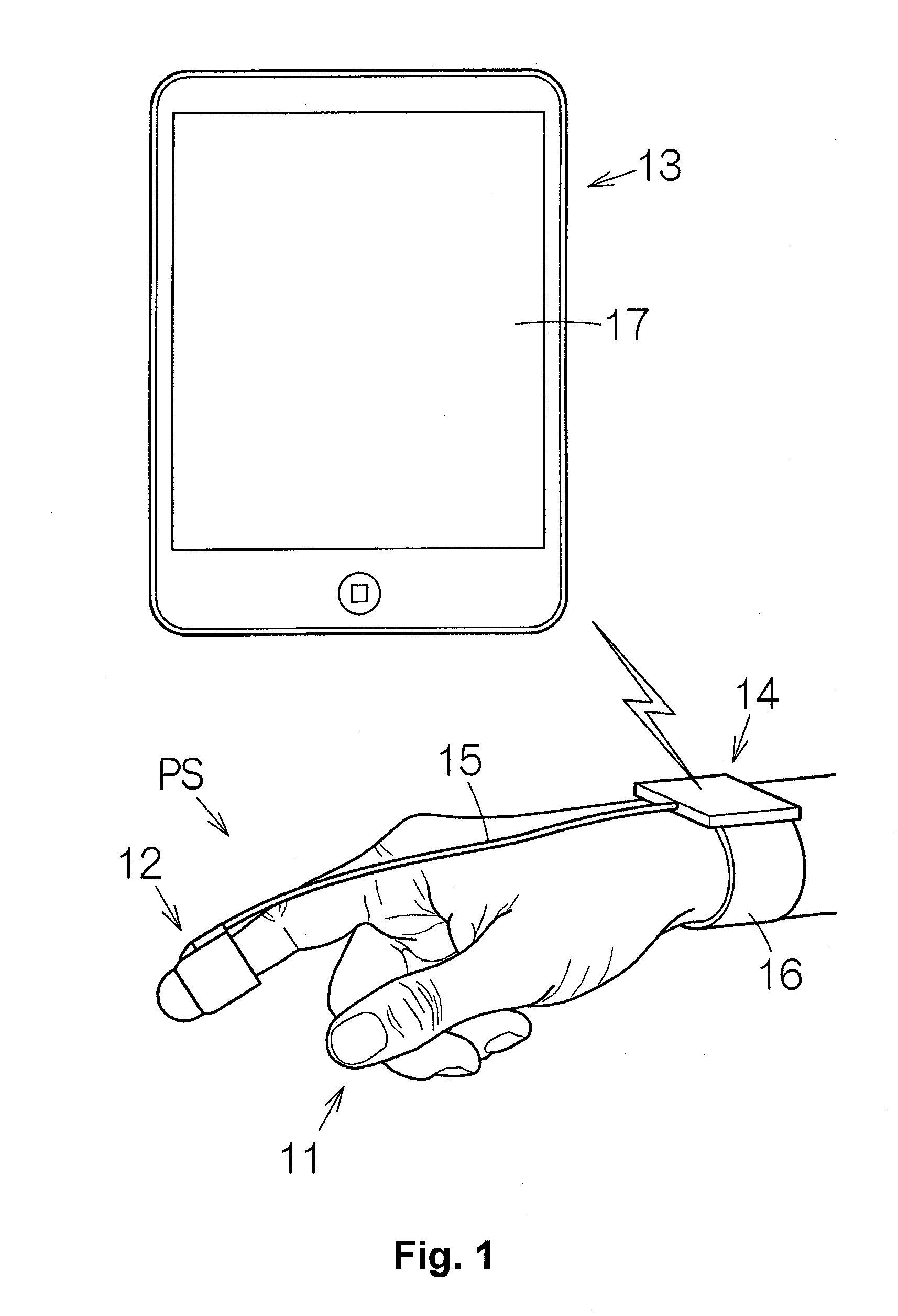
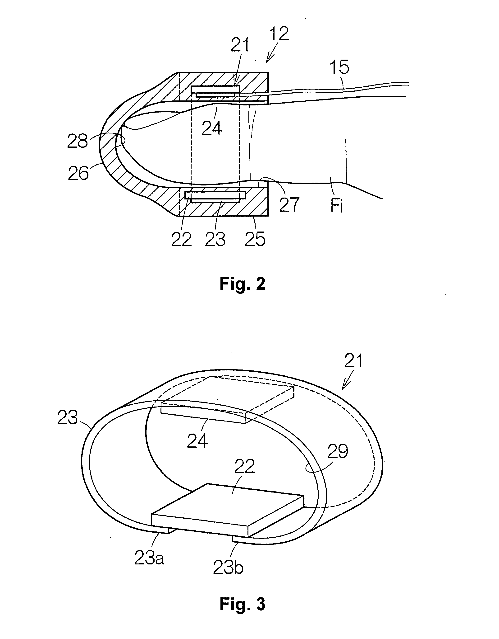
[0076]FIG. 9 schematically shows an annular body unit 21a according to a second embodiment of the present invention. The ultrasonic diagnostic device 11 can use the annular body unit 21a instead of the above-described annular body unit 21. In this second embodiment, the annular body is constructed of the element chip 22 and a pair of flexible printed substrates 81 (examples of a first flexible wiring section and a second flexible wiring section). Each flexible printed substrate 81 is connected to the element chip 22 at a first end 81a, and connected to the control circuit 24 at a second end 81b. The element chip 22, the flexible printed substrates 81, and the control circuit 24 collectively surround the space 29. The other configurations are similar to those of the first embodiment. The configurations or structures that are equivalent to those of the first embodiment are given the same reference numerals and the overlapping explanations are omitted. In the same ...
third embodiment
(5) Annular Body Unit
[0077]FIG. 10 schematically shows an annular body unit 21b according to a third embodiment of the present invention. The ultrasonic diagnostic device 11 can use the annular body unit 21b instead of the above-described annular body unit 21. In this third embodiment, the annular body is constructed of a single flexible printed substrate 82 alone. A first end 82a of the flexible printed substrate 82 is connected to a second end 82b of the flexible printed substrate 82. The flexible printed substrate 82 surrounds the space 29 alone. The element chip 22 and the control circuit 24 are mounted on a surface of the flexible printed substrate 82. In order to connect the lower electrode terminals 41 and the upper electrode terminals 42 to the signal lines 43 and 44 on the flexible printed substrate 82 in the element chip 22, conductive via holes may be formed in the flexible film 49, the substrate base 47 and the reinforcing plate 55 such that the conductive via holes pene...
fourth embodiment
(6) Annular Body Unit
[0078]FIG. 11 schematically shows an annular body unit 21c according to a fourth embodiment of the present invention. The ultrasonic diagnostic device 11 can use the annular body unit 21c instead of the above-described annular body unit 21. In this fourth embodiment, the annular body is constructed of a single flexible printed substrate 83 alone. The flexible printed substrate 83 has a pair of connecting pieces 84 that extend from the annular body in a direction orthogonal to a circumferential direction of the annular body and located in opposed positions of the annular body. The element chip 22 is connected between tip ends of the connecting pieces 84. When a finger Fi of an operator enters the space 29 of the annular body, the element chip 22 can be positioned at the tip end of the finger Fi. Although not shown in FIG. 11, the control circuit 24 is preferably connected to the flexible printed substrate 83 in the same manner as described in the first embodiment...
PUM
 Abstract
Description
Claims
Application Information
 - R&D
- Intellectual Property
- Life Sciences
- Materials
- Tech Scout
- Unparalleled Data Quality
- Higher Quality Content
- 60% Fewer Hallucinations
Browse by: Latest US Patents, China's latest patents, Technical Efficacy Thesaurus, Application Domain, Technology Topic, Popular Technical Reports.
© 2025 PatSnap. All rights reserved.Legal|Privacy policy|Modern Slavery Act Transparency Statement|Sitemap|About US| Contact US: help@patsnap.com


